Recently I was doing some audio performance tests on a "tape" - a ¼" analog magnetic tape. Was just curious to see what kind of response, distortion, noise, etc.. a tape really is home to. Have not really 'seen' it yet.
So I pulled my trusty RT-707 out of the rack and decided to do these tests in a loopback mode using RMAA on my PC. The recording was in monitor mode i.e. whatever was being recorded was getting played back right away. And that played back signal was being analzed by RMAA.
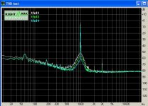
I have some questions about a couple of results. First lets look at the Noise/SNR. Just for reference I included the LineIn->LineOut loopback test of just the electronics (minus the tape) which is in green. The tape response is in white.
A couple of things that I'd like to figure out are -
What could be causing the sudden loss of snr below about 600hz ?
As you can see this is accompanied with a 10hz harmomic all across from 10hz to about 600hz, and then it suddenly disappears. What could this be ?
Could these two be related ? Although I think I probably know what that 10hz harmonic is. Its the motor (or the speed servo control) because I can hear a very faintly audible tick in the headphones/speakers and the audible occurense seems to match the visual occurence on a realtime scope function.
Another thing I am trying to confirm is -
While doing these test I realized that RMAA is using a Logarithmic sweep/tone signal to check frequency response. Would it be correct to say that a Logarithmic Sweep sine signal - the one in which amplitude level drops with increase in frequency - is unsuitable for measuring the frequency response of a tape ? (because of the tape's variable sensitivity to frequency ?)
Heads had been cleaned and properly demagnetized before start of these tests. The tape however was an old but lightly used Maxell UD35-90, visibly in good condition nevertheless.
TiA!
So I pulled my trusty RT-707 out of the rack and decided to do these tests in a loopback mode using RMAA on my PC. The recording was in monitor mode i.e. whatever was being recorded was getting played back right away. And that played back signal was being analzed by RMAA.
I have some questions about a couple of results. First lets look at the Noise/SNR. Just for reference I included the LineIn->LineOut loopback test of just the electronics (minus the tape) which is in green. The tape response is in white.
An externally hosted image should be here but it was not working when we last tested it.
A couple of things that I'd like to figure out are -
What could be causing the sudden loss of snr below about 600hz ?
As you can see this is accompanied with a 10hz harmomic all across from 10hz to about 600hz, and then it suddenly disappears. What could this be ?
Could these two be related ? Although I think I probably know what that 10hz harmonic is. Its the motor (or the speed servo control) because I can hear a very faintly audible tick in the headphones/speakers and the audible occurense seems to match the visual occurence on a realtime scope function.
Another thing I am trying to confirm is -
While doing these test I realized that RMAA is using a Logarithmic sweep/tone signal to check frequency response. Would it be correct to say that a Logarithmic Sweep sine signal - the one in which amplitude level drops with increase in frequency - is unsuitable for measuring the frequency response of a tape ? (because of the tape's variable sensitivity to frequency ?)
Heads had been cleaned and properly demagnetized before start of these tests. The tape however was an old but lightly used Maxell UD35-90, visibly in good condition nevertheless.
TiA!
percy,
The low frequency "noisiness" is probably related to FFT windowing. Have you tried using pink noise instead of sweep tone? That should give more realistic view of frequency response.
The low frequency "noisiness" is probably related to FFT windowing. Have you tried using pink noise instead of sweep tone? That should give more realistic view of frequency response.
this is a noise level test - there is no signal.
And it is not fft windowing. It is a very clear 10hz harmonic. Otherwise why isnt windowing a problem in the "reference" (green) chart ?
And it is not fft windowing. It is a very clear 10hz harmonic. Otherwise why isnt windowing a problem in the "reference" (green) chart ?
Why 0dbm ? Wouldn't that be too much for that tape ? I'd imagine -10db to -20db would be where I'd like the signal to be ?
I can post the thd measurement later today, but how would that help ? I guess I am trying to understand what exactly are you looking for from the thd measurement ?
I can post the thd measurement later today, but how would that help ? I guess I am trying to understand what exactly are you looking for from the thd measurement ?
You will see the distortion and noise characteristics at 0 dB. 0 dB gives 3% distortion if well calibrated. The S/N can also be evaluated from that graph. On the other hand, frequency response can be measured at -10 dB (reel-to-reel) or at -20 dB (cassette).
I'd also like to post the waveform of the spectrum.
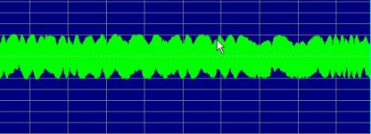
This is a small portion of the recorded waveform - not zoomed in all the way - as I wanted to show you the "notches" at the top and bottom of the waveform.
What does that indicate ? An issue with the tape, or the heads, or bias ??
Higher the frequency of the signal the more rougher they get. As you can see in the next one which is a 16Khz signal.
Attachments

Percy,
The "skirt" is phase modulation of the test signal, caused by wow and flutter. It does not widen as the level is increased, just shifted upwards along with the test tone. If that is a Pio RT707, the dual-capstan explains the low level of wow and flutter. The notches in the waveform indicate worn tape, inadequate tape tension or both (dirty head excluded). Another interesting test would be to connect the L/R channel outputs to the X/Y inputs of an oscilloscope. You should get a stable 45° straight line. If there is some phase difference between the channels or the playback head is misaligned re the record head, the line becomes elliptical. It is a tough test at 16 kHz... Also the playback level at 1 kHz and at 16 kHz should be about the same, if recorded at -10 dB.
The "skirt" is phase modulation of the test signal, caused by wow and flutter. It does not widen as the level is increased, just shifted upwards along with the test tone. If that is a Pio RT707, the dual-capstan explains the low level of wow and flutter. The notches in the waveform indicate worn tape, inadequate tape tension or both (dirty head excluded). Another interesting test would be to connect the L/R channel outputs to the X/Y inputs of an oscilloscope. You should get a stable 45° straight line. If there is some phase difference between the channels or the playback head is misaligned re the record head, the line becomes elliptical. It is a tough test at 16 kHz... Also the playback level at 1 kHz and at 16 kHz should be about the same, if recorded at -10 dB.
Sorry, I just read more about the RT-707 on the web and it is a single capstan direct drive machine. The left roller is said to be a flutter filter.
the RT-909 was dual capstan belt drive. the 707 & 701 were single capstan units that "look" like dual.
The Rt-707/701 has a bad capstan AC servo, if you play back a 1kHz tone you can hear it. I sold my RT-707 in the mid eighties because of that. Looks like a tank ,but it is a flawed design. The wave form as oshifis mentioned is looks like dropout, the recording probably was made on an old used tape.
Hello!
I have TEAC V-7000 in my set up here, and I have problems with left capstan(pinch roller) because I have no stable playback,when the tape is recorded and after play that same tape I have to readjust the head azimuth, so it is a mechanical problem.I removed left pinch roller and now it is working just with the main capstan and pinch roller.
Do anyone knows where to get this parts(new) and also is it possible to buy somewhere original Head for TEAC V-7000???
Try www.tapeheads.net - a new forum that might have someone with an answer to your question about parts for the teac. The topic of this thread would be of interest over there as well.
- Status
- Not open for further replies.
- Home
- Source & Line
- Analogue Source
- Tape Tests