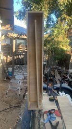
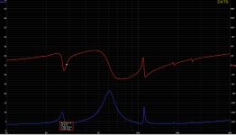
Not sure if these are ‘TL’ or tapped pipe? the sims and impedance plots are somewhere in between .
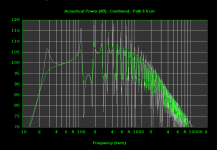
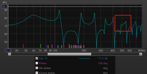
Did the horrible TS parameters and actual driver Fs of 59.4 (instead of 45) gimme that hump In the middle of the babdwidth?
Did the horrible TS parameters and actual driver Fs of 59.4 (instead of 45) gimme that hump In the middle of the babdwidth?
Attachments
-
 F1D375D5-19D3-414F-8537-09B9FF3A4418.jpeg623.8 KB · Views: 182
 -
 019FF6F7-3966-4C1B-B156-7D4B63999AF9.jpeg477.5 KB · Views: 179
 -
 91E2936C-18A3-46CD-812D-72418CB26944.jpeg454.7 KB · Views: 187
 -
 A568A0A8-F3E7-4D90-960A-4C3EFE9FB95C.png6.3 KB · Views: 167
 -
 5877CFB4-D876-4505-AC7A-1FF7C92CC8DA.png14.7 KB · Views: 180
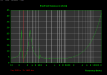
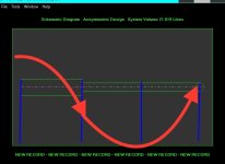
Tapped horn sim is the more agreesive looking /lossless sim, TL with QL set @ 15 is the other .
Horn response nailed the Fb and pioe resonances/cancelations yet again
Horn response nailed the Fb and pioe resonances/cancelations yet again
Attachments

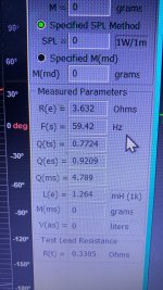
Jeez…. Ts parameters are way off, need about 4 years at xmax to settle in 😥
Attachments
Last edited:
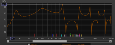
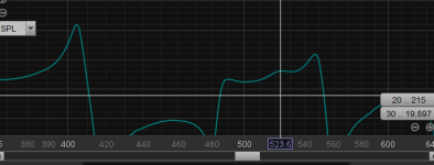
Is this the driver offset position (between the ‘15/4 and 17/4‘ resonances ? There’s a brace in that area too
Attachments
Did you push the driver past Xmax (18.5mm peak to peak) before measuring?Did the horrible TS parameters and actual driver Fs of 59.4 (instead of 45) gimme that hump In the middle of the babdwidth?
Plug in your "Measured Parameters" into the Hornresp sim and see if it results in the difference you measured.
Technically 'tapped': T-TQWT whereas the Jensen is a T-TL.Not sure if these are ‘TL’ or tapped pipe? the sims and impedance plots are somewhere in between .
Did the horrible TS parameters and actual driver Fs of 59.4 (instead of 45) gimme that hump In the middle of the babdwidth?
Well the math 'says':
0.42*45*0.49^-0.96 = ~37.49 Hz
0.42*59.42*0.7742^-0.96 = ~31.98 Hz
So it's apparently the much higher Qts wanting a longer and probably larger, pipe.
I guess I should have spelled out what I meant last week:(I dunno what im doing when measuring and am just trying to verify the sim)
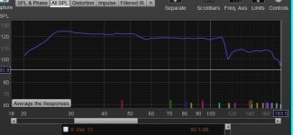
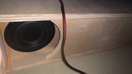
As you found, the near field response you measured with the random placement in the "vent" or mouth is not what the cabinet response is.
You could easily get a half dozen different looking response curves moving the mic around in the near field.
As Pat Brown explained, the far field is reached at the distance from the source where the path length difference for wave arrivals from points on the device on the surface plane perpendicular to the point of observation are within one-quarter wavelength at the highest frequency of interest.
That criteria can be satisfied up to 210Hz for a subwoofer with a one square meter face measured at one meter with a measurement mic on the ground plane.
For "half space" ground plane measurements the mic should be on the ground at one meter (or more) from the acoustic center, and both should be as far from any large reflective objects as possible to minimize their effect.
Art

Indeed!For "half space" ground plane measurements the mic should be on the ground at one meter (or more) from the acoustic center, and both should be as far from any large reflective objects as possible to minimize their effect.
Reminds me of Altec's free space measurement 'jig' (A4 VoTT system w/210 horn cab, dual 515B) 84" H x 80.5" W x 39.5" D).
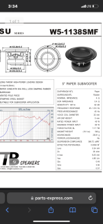
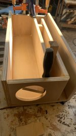
Looks like a single fold tapped tapered quarter wave tube or pipe (T-TQWP or T-TQWT) to me.
Basically, a negative flare tapped horn or a negative flare port BP6S.

Double fold version.
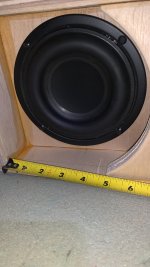
9" high x 16" wide throat.
5" high x 16" wide mouth.
10 foot horn.

Basically, a negative flare tapped horn or a negative flare port BP6S.
Double fold version.
9" high x 16" wide throat.
5" high x 16" wide mouth.
10 foot horn.
Last edited:
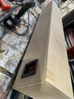
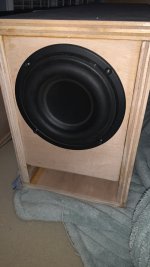
It Seems to sound a lot better at high SPL levels (to fill a small room with bass withthis little driver) than if in a similar Tuned bass reflex. I dunno if it’s the shape of the chamber/port or the high qts driver or….
Attachments
👍🏼👍🏼Looks like a single fold tapped tapered quarter wave tube or pipe (T-TQWP or T-TQWT) to me.
Basically, a negative flare tapped horn or a negative flare port BP6S.
View attachment 1249141
Double fold version.
9" high x 16" wide throat.
5" high x 16" wide mouth.
10 foot horn.
View attachment 1249139
The greater the power input, the greater its acoustic (TL/horn) loading/damping of the driver = less excursion for a given SPL.
👍🏼👍🏼 ??
👍🏼👍🏼 ??
It Seems to sound a lot better at high SPL levels (to fill a small room with bass with this little driver) than if in a similar Tuned bass reflex. I dunno if it’s the shape of the chamber/port or the high qts driver or….
Bandpass enclosures rule!
I wish I could send recorded sound/videos off a phone that demonstrated the difference now that I’ve built both with the identical driver and amp, etc. it’s strange…. The bass reflex port/driver goes thud while the tapped pipe is still smoothThe greater the power input, the greater its acoustic (TL/horn) loading/damping of the driver = less excursion for a given SPL.
👍🏼👍🏼 ??
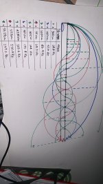
I just draw it to scale in mm and all the freqs that ‘fit’ in the ‘pipe‘ that are either a resonance or perfectly ‘in phase or out’ at the other side of the driver (and vent exit in this case) ?
Attachments
Well, it is by definition a 'one note' 'band stop' acoustic filter Vs a TL
Folks are using these filters in exhaust systems to prevent droning at highway speeds.
- Home
- Loudspeakers
- Subwoofers
- Tangband 5” Tapped tapered QW tube…