Could someone please model or simulate a series X-over for the Tang-band W4-1720 used with a SB Acoustics tweeter here is the data > http://www.solen.ca/pdf/sb/sb25stncc0004.pdf See also > http://www.parts-express.com/pdf/264-872s.pdf Any help would be greatly appreciated ! Thank-you for any or all efforts !
"Anyone who has never made a mistake has never tried anything new."Could someone please model or simulate a series X-over for the Tang-band W4-1720 used with a SB Acoustics tweeter here is the data > http://www.solen.ca/pdf/sb/sb25stncc0004.pdf See also > http://www.parts-express.com/pdf/264-872s.pdf Any help would be greatly appreciated ! Thank-you for any or all efforts !
Would the formulas in this pdf work for a ball-park series X-over ? Link > http://www.passdiy.com/pdf/CurrentSo...erNetworks.pdf
An externally hosted image should be here but it was not working when we last tested it.
The amp I plan to use is a Pass F4 clone with a hi-gain SE tube preamp !You can get a "ballpark" crossover calculation from a tool like this:
2-Way Crossover Designer / Calculator
It's not going to be flat with your drivers though, unless the drivers are razor flat and have the impedance curve of a resistor :S
I've found success recently with learning how to use Speaker Workshop and either finding my driver's FRD/ZMA files online, or making my own with SPLTrace.
I'm currently taking the time to learn how to use Speaker Workshop and all the FRD tools stuff and it's turning out to be a valuable skill. Give it a whirl!
The X-over calculator in your link does not do series x-overs, all though I believe Speaker Workshop will ! My problem is I do not have access to a computer that I can down-load anything into. I should have my own back up buy late September. Thank-you for the assistance !
The X-over calculator in your link does not do series x-overs, all though I believe Speaker Workshop will ! My problem is I do not have access to a computer that I can down-load anything into. I should have my own back up buy late September. Thank-you for the assistance !
Very welcome sir!
Is this forum not a collective of great works, designs and innovative people ? Come-on people, someone could surely run a simulation or two ! If nothing else it could turn into a really great thread ! Again any help would be greatly appreciated thanks !
So I looked up the frequency response of that little woofer and it looks to me as though it can be used full range, as it's pretty much good up to 20khz.
Perhaps you can just hook it right up and save the tweeter for another project 🙂
Edit: they say 8khz, probably because it gets a little bumpy from cone breakup. I'd model it for you, but it wouldn't be current drive.
Perhaps you can just hook it right up and save the tweeter for another project 🙂
Edit: they say 8khz, probably because it gets a little bumpy from cone breakup. I'd model it for you, but it wouldn't be current drive.
Last edited:
If you could model it with the SB Acoustics tweeter that would be awesome ! Current drive is just on of the benefits of series X-overs ! I very much appreciate your efforts thus far thank-you !
Eddited from post #7Is this forum where we have a collective of great works, designs and innovative people ? Come-on people, someone could surely run a simulation or two ! If nothing else it could turn into a really great thread ! Again any help would be greatly appreciated thanks !
The X-over calculator in your link does not do series x-overs, all though I believe Speaker Workshop will ! My problem is I do not have access to a computer that I can down-load anything into. I should have my own back up buy late September. Thank-you for the assistance !
The starting point for a series XO are exactly the same as a parallel XO.
Best to just get some parts and start playing.
dave
That is really great, do you have a graph showing X-over and slopes, impedance and phase ? This gives me a idea how the two will interact ect... Thank-you very much !
That is really great, do you have a graph showing X-over and slopes, impedance and phase ? This gives me a idea how the two will interact ect... Thank-you very much !
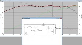
Yeah, it's kinda in there, the dashed red line is phase, thick red is overall frequency response, green is the tweeter's response and thin black is the woofer. Note that the tweeter polarity is inverted.
Edit: let me go coax it into giving me impedance, my windows machine is upstairs.
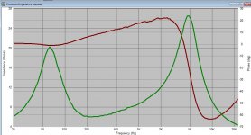
I honestly don't know what to look for were the phase or impedance is concerned ! Could you post the response graph with-out the schematic ? To me everything looks really awesome !
I honestly don't know what to look for were the phase or impedance is concerned ! Could you post the response graph with-out the schematic ? To me everything looks really awesome !
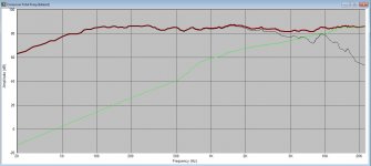
Sure thing, here it is 🙂
Bear in mind, I had to trace the frequency response by hand with SPLTrace using the manufacturer's charts, so it might be a little lumpier than it is in reality.
Attachments
Last edited:
That graph looks really quite good ! The only thing I see is it looks to be X-overed around 6K ! the problem with that high of a x-over is the driver C-T-C spacing would half to be 2.0 inches. I had discovered a chart for C-T-C spacing vs frequency while reading some time ago. If I can find the link I will post it for you. From what I understand those 2 drivers together need to be X-overed somewhere between 2.0 & 3.5K. Here is were I had first read of it see post 14 & 15 ect... Link > http://techtalk.parts-express.com/showthread.php?t=225401
Last edited:
That graph looks really quite good ! The only thing I see is it looks to be X-overed around 6K ! the problem with that high of a x-over is the driver C-T-C spacing would half to be 2.0 inches. I had discovered a chart for C-T-C spacing vs frequency while reading some time ago. If I can find the link I will post it for you. From what I understand those 2 drivers together need to be X-overed somewhere between 2.0 & 3.5K.
I modeled it to be at 4k, it's pretty close. Well, maybe not. I tried to get rid of the cone breakup that was happening from that woofer, but you should be able to shift the xo point around by changing the coil values up some and playing with the cap values
Please don't think I,m knocking your efforts, I,m not, just trying to provide some help in this endeavor ! I really don't know enough to say whats good or bad. As I had said your work looks great. I had posted this combo in several other forums and you are the first to actually offer real assistance ! Again thanks Here is a link for someone using the same woofer > http://www.lonesaguaro.com/speakers/TB4V/Piccolata.html See also > http://sites.google.com/site/undefinition/speedster
Last edited:
- Status
- Not open for further replies.
- Home
- Loudspeakers
- Multi-Way
- Tang Band W4-1720/Series X-over help needed !