Hi All,
I’m in the process of rebuilding the voltage regulator for the preamp section in my Tandberg 3012 integrated amp. Over time, it has been damaged by heat and there have been some repairs that also have failed, and now some of the circuit traces are lifting from the board. The last person working on it has given up, as the time he needs to put into it would be problematic for both of us. He is of the opinion that one or more of the transistors in this section is failing and that is causing a voltage imbalance and that is causing the amp to shut down.
I, however have some covid-time available, and a few craft skills—although I need some advice in the electronic realm.
Here’s the plan as it stands:
I’ll pull all the semiconductors and get new ones. If I can get them off the board without wrecking it, I’ll replace them in the current board. If it’s beyond repair, I have a plan to make a small new board with all the regulator parts and stand it off the current board. I’ll be creating a heatsink for the power transistors, and move them to the top of the board to perhaps dissipate heat better (all the other parts are mounted on the bottom). And that amplifier is biased into class A, so it generally runs warm, which is likely the reason the regulator failed to begin with. I’m thinking of building a low-profile plinth with a fan to keep some air moving through the whole thing.
So far, so good?
Of course, since this is c. 1990 equipment, the transistors and zeners seem hard to find.
Here’s the list (Sorry, format here won't let me tab this into columns):
Part # Type Original Replacement. Alt
CR418 Zener BZX79-C62 1N565B
CR415 Zener. BZX83-C12 1NTE5021A 1N963B
Q435 NPN/TO92 BC447B BC449
Q436 PNP/TO92. BC448B BC450 BC450B
Q439 NPN/TO202. BD419 BD139 CEN-U57
Q440 PNP/TO202. BD420 BD140 CEN-U07
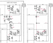
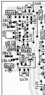
I haven’t run down all the numbers on these replacements beyond the general voltage and current specs. If anyone has thoughts on particular choices or better ones, I’d appreciate the input. Regulator is +- 62V. Circuit diagram and board layout attached.
I’d prefer to keep as close to stock as I can, but would I be much better served by an all-new regulator design/circuit, especially as I’m already considering building and mounting a new board? I do want to fix this once and for all. If so, any recommendations for a +-62V regulator circuit?
Oh, and does anyone know why there are two sets of 1N4148 diodes in series? What’s the purpose?
I’m in the process of rebuilding the voltage regulator for the preamp section in my Tandberg 3012 integrated amp. Over time, it has been damaged by heat and there have been some repairs that also have failed, and now some of the circuit traces are lifting from the board. The last person working on it has given up, as the time he needs to put into it would be problematic for both of us. He is of the opinion that one or more of the transistors in this section is failing and that is causing a voltage imbalance and that is causing the amp to shut down.
I, however have some covid-time available, and a few craft skills—although I need some advice in the electronic realm.
Here’s the plan as it stands:
I’ll pull all the semiconductors and get new ones. If I can get them off the board without wrecking it, I’ll replace them in the current board. If it’s beyond repair, I have a plan to make a small new board with all the regulator parts and stand it off the current board. I’ll be creating a heatsink for the power transistors, and move them to the top of the board to perhaps dissipate heat better (all the other parts are mounted on the bottom). And that amplifier is biased into class A, so it generally runs warm, which is likely the reason the regulator failed to begin with. I’m thinking of building a low-profile plinth with a fan to keep some air moving through the whole thing.
So far, so good?
Of course, since this is c. 1990 equipment, the transistors and zeners seem hard to find.
Here’s the list (Sorry, format here won't let me tab this into columns):
Part # Type Original Replacement. Alt
CR418 Zener BZX79-C62 1N565B
CR415 Zener. BZX83-C12 1NTE5021A 1N963B
Q435 NPN/TO92 BC447B BC449
Q436 PNP/TO92. BC448B BC450 BC450B
Q439 NPN/TO202. BD419 BD139 CEN-U57
Q440 PNP/TO202. BD420 BD140 CEN-U07
I haven’t run down all the numbers on these replacements beyond the general voltage and current specs. If anyone has thoughts on particular choices or better ones, I’d appreciate the input. Regulator is +- 62V. Circuit diagram and board layout attached.
I’d prefer to keep as close to stock as I can, but would I be much better served by an all-new regulator design/circuit, especially as I’m already considering building and mounting a new board? I do want to fix this once and for all. If so, any recommendations for a +-62V regulator circuit?
Oh, and does anyone know why there are two sets of 1N4148 diodes in series? What’s the purpose?
Attachments
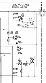
This s a simple zener referenced dual regulator. Transistors with diode strings
form constant current sources.
It powers up when both input voltages are present, by action of Q 435, Q 436.
This way it was done at the time. It will be least trouble to recreate it as it was,
I think.
It is not short-circuit proof and will be destroyed by excessive load. Check the
output side.
form constant current sources.
It powers up when both input voltages are present, by action of Q 435, Q 436.
This way it was done at the time. It will be least trouble to recreate it as it was,
I think.
It is not short-circuit proof and will be destroyed by excessive load. Check the
output side.
Last edited: