If your whole goal is to just reduce the volume you could always put a voltage divider on the input. running your DAC at 1% is hurting resolution on your sound card as it stands by lowering it so much.
you could always also build an actual volume control on the amplifier
Reduce the amplifier gain as much as you can before tho as high gain will be quite sensitive to noise.
To help get rid of the noise, replace all your wires with shielded cabling if needed. I had to do that on both my speaker and input sides
You have less gain inside the feedback loop, so less feedback - the feedback resistor could be reduced to get feedback to the original amount. Unbypassed cathode resistor on the first stage should be fine. You did adjust the voltage divider values in the paraphase splitter for the lower gain of the 6CG7?
OK the schematic is finally coming along. I have been trying to draw it in Google Sketchup, as it is what I know best. The problem was it was hard to see zoomed back because the program was putting these little line "extensions" on all the corners etc.
The problem was solved by switching the actual drawing template from "Architectural" to "Plan View", much easier to see now.
The problem was solved by switching the actual drawing template from "Architectural" to "Plan View", much easier to see now.
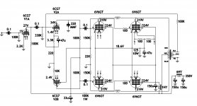
So here is a schematic for better or worse. You can see the tinkering I was doing in the front end from last year. Some real funny voltages there now.
On the plus side I have a nice system figured out for drawing schematics in Google. Turn out OK for the first go. I will have to see how it looks uploaded on here, hopefully you can read the values.
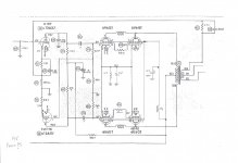
I also uploaded a schematic for reference. It's basically the stock Magnavox AMP132 with the screen choke drawn in, compliments of ab00ez.
So it looks like I really ventured of with now real plan. I changed the heater wiring for the 6CG7 to replace the 12AX7 and added the extra socket for the additional 6CG7. It was about this time that the noise started. It was silent before that.
Oddly enough it sounds pretty good right now in this state, aside from the other noise and the too much gain thing.
So have a look and let me have it! lol
On the plus side I have a nice system figured out for drawing schematics in Google. Turn out OK for the first go. I will have to see how it looks uploaded on here, hopefully you can read the values.
I also uploaded a schematic for reference. It's basically the stock Magnavox AMP132 with the screen choke drawn in, compliments of ab00ez.
So it looks like I really ventured of with now real plan. I changed the heater wiring for the 6CG7 to replace the 12AX7 and added the extra socket for the additional 6CG7. It was about this time that the noise started. It was silent before that.
Oddly enough it sounds pretty good right now in this state, aside from the other noise and the too much gain thing.
So have a look and let me have it! lol
Attachments
Sigh, maybe I will just go back to the 12AX7 in the original schematic.
Even if I bias the 6CG7's right, I'm not sure how "proper" it is for the amp. It was suggested by many as a good swap so I thought I might have some support regarding the switch.
Let this be a warning not to ruffle feathers with diyAudio moderators and their cronies.
With the exception of Kevin, the rest have completely shunned me lol.
Well maybe I can get myself out of this mess, I am going to try a few things today., I would like to continue to use the 6CG7's because they do sound nice, even in their current arrangement. Plus I have the "3rd" socket now which I don't really want to leave empty.
Last edited:
I can be such a whiner at times lol.
I have a drawing coming along with suggestions from the previous pages.
Now that I have the drawing it makes it easier to visualize it, as it was "all in my head" before. 😉
-Individual RC bias, with possible pots.
-Adjust the feedback way down, I had the opposite going on with 100K vs. the 27K stock rfb. I will pop in a 10K and see what happens.
-unbypass the inverter.
-gridstoppers
If that does not work out, I might try a cathode follower front end. I looked into it more, might go this way because frankly I don't know what to do with this paraphase inverter with the 6CG7 in that spot.
There I feel better now.
Last edited:
Well I made some changes. too many at once I suppose.
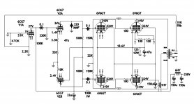
I updated the schematic, (I had the feedback drawn in the wrong part)
-I put 33K gridstoppers on the first 6CG7.
-changed the grid resistor from 100K to 470K. (I know this makes it louder, just trying to get it closer to the way it was)
-lowered the feedback resistor from 100K down to 10K.
Now the amp squeals/howls. I only had it on for a moment, not sure if it's oscillating or if it is feedback howl. I will have to go back and change something. else. I still am going to raise the voltage back up on the 6CG7.
Attachments
Nope it wasn't feedback howl, it made a god awful noise when I flipped the plate leads around. lol
OK "Davesnothere's" tip about the gridstoppers worked. I should have known better and do use them in guitar amps, it was something I overlooked because the amp was silent at one point in time without them.
Now I finally got rid of the noise again with the 33K gridstoppers.
I also changed the feedback resistor to 22K, which is what it was on the original schematic. I have tried lowered, but it made those noises.
I also switched the plate wires back to normal.
So I am half way there. I'm not a hundred percent sure, but I think the volume situation is a little tamer now.
Attachments

Nothing says good morning like a pot of coffee, an empty house and a little Terror and Hubris in the House of Frank Pollard.
Just noting some changes an higher volume levels. The bass is slightly different now due to the power supply changes and the additional negative feedback. Speed has improved a bit, although now it does not seem as "loose" as it was. It was not "loose" in a sloppy way, it was "loose" in a dynamic kinda way.
The bass is slightly better now, mainly due to the improvement in the ability to play double kick bass tighter now. Some of this stuff is hard to play and have sound good on most systems I have tried. Slayer always sounds warm and half decent. Lamb of God on the other hand can sound like garbage falling down stairs rather then controlled chaos on most stereos. Although it always sounds pretty good through an iPod.
I should mention I un-bypassed the 6CG7's, I forgot to mention that in an earlier post.
now for some more fun. remove 47 uf cap from cathode circuit but leave it still connected to the heater referencing resistors and ground. Just the resistor on the output. like or dislike? for an altec-ish sound, leave the heater ground referencing circuit disconnected from the cathode but still through the 47 uf cap, and bypass the cathode with a 220uf cap are we cooking with hot grease yet?
oh yea since you increased the cathode capacitance at the output, put 1 uf cap across the .01 input coupling cap, increase the the others to 2.2 uf
Hmm sounds interesting, I will try it later on today when I get a chance.
What does the 47u cap do when I leave the cap hooked up to the heaters, but not the cathode resistor?
Earlier on I did remove the 0.1 coupling from the input of the first 6CG7 stage.
All the other coupling caps are 0.1 as well, but maybe your saying to change them to 0.22, which I do have on hand.
I have actually wanted to try the bigger coupling caps. It was my understanding earlier on that increasing the coupling caps on this Magnavox circuit would not yield any more bass. Something to do with it removing the bass early on then adding it back into the circuit near the end.
Anyhow I suppose I am far enough away from the original circuit now!
post 25
I'm curious: the first set of push pull 6V& has no grid stoppers whilst the 2nd has...this doesn't seem right. All should have grid stoppers.Correct ?
I'm curious: the first set of push pull 6V& has no grid stoppers whilst the 2nd has...this doesn't seem right. All should have grid stoppers.Correct ?
I double checked the Magnavox AMP142 and AMP132 schematic. They both show it like that. You can see it in the semi/stock AMP132 image posted beside it. (Post #25).
That appears to be the only gridstopper on the whole circuit.
100 ohm seems a little low, but maybe it's fine in that particular stage.
I took care of 95% of the computer noise with the 33K gridstopper I added on the input.
That being said I don't mind tossing another set of gridstoppers on the first set of 6V6, if you think it would benefit.
What does the 47u cap do when I leave the cap hooked up to the heaters, but not the cathode resistor?
I have actually wanted to try the bigger coupling caps. It was my understanding earlier on that increasing the coupling caps on this Magnavox circuit would not yield any more bass. Something to do with it removing the bass early on then adding it back into the circuit near the end.
Anyhow I suppose I am far enough away from the original circuit now!
the 47 uf cap still to the heaters provides an AC ground for the hum canceling circuit (two resistors across heater). when you increase the cathode bypass to 220uf it basically grounds the cathode in AC. the power bandwidth response of the tube increase as inter-electrode capacitance product is now a smaller value (due to the tube being in series with the cap). When you have no bypass cap the response is more linear to the calculations and gain is lowered because the AC ground (signal ground) as well as the DC ground (bias) in the cathode circuit is going through the resistor. This effect is in all common cathode, common emitter, and common drain circuits.
Also glancing over, the post, you mentioned noise from the computer.One way is usually caused by a dynamic rectification of the input signal tube's signal feeding back in the form of dc which in turns alters the sound card's op amp zero crossing causing common mode distortion (problem only exists when signal present). Another way is cause of this is poor dc isolation due to unbalance cable run and grounds of interconnecting devices. And last, the switchmode power supply is throwing trash on the ground. the first two can be solved by putting a 1uf (thats 1UF not .1 or .01) in series with the grid and input after the grid stop resistor. The second can be fixed by opening up the computer and installing .1 uf capacitors on the 12V and 5V rails to ground.This technique I call "grounding the AC grounds" ( dc power and dc supply grounds are consider grounds to AC signals)
Last edited:
Thanks for your response.
I now know what you mean about leaving the 47u in. I actually have some .047 caps just for that reason.
I have the heaters disconnected, still through the 47u to ground.
I added some 220u bypass caps to the common 6V6 cathodes.
I'm just about done recapping the couplers to .22 while I'm in there, I'll try it out shortly.
As far as the noise, it's not an issue now, the 33K gridstoppers got rid of 95% of the noise. Although I might toss some .1u in later with maybe a 68K gridstopper to future-proof it. The .1 cap could be fairly low voltage I'm assuming?
on the computer rails- yes it dosen't matter, if you have some cheapy 50V go for it. I usually use wima's for them as they are low quality to my standards and somebody raved about them so I bought some from mouser. Needless to say, I did find a purpose for them. when it comes to caps I use 1/3 more than the voltage applied for. and ploys there usually way beyond my minimum voltage standards.
Last edited:
OK so I like what I hear so far. It makes a difference (more bass) on most songs I have played so far.
This is what I was looking for. See I'm not a "bass" head but I would have liked to turn the bass up slightly before, for listening at low volume levels and for movies. I have found out as some of you may already know the nasty distortion a computer EQ adds. For that reason I have been running it flat.
So ya it sounds good. The bass is just right now, it's filled in nicely!
I don't know how much bass was gained by the new .22 coupling caps, but they do sound nice so now harm that way.
A little brighter, maybe a little more sizzle then the .1's, see what they sound like after some use.
I am going to get my schematic updated later on and start thinking about getting the plate voltages on the 6CG7's more inline.
It's hard for me to find info on a 6CG7 paraphase inverter vs. the stock 12AX7 paraphase inverter.
It sure does sound nice though.
- Status
- Not open for further replies.
- Home
- Amplifiers
- Tubes / Valves
- Tame the beast.