I built this pair of speakers for my brother’s workshop/garage. He has speakers on his workbench on either side of a PC monitor, and he is often standing at the bench as well as sitting. He needs the speakers to sound good in the nearfield, as well as being able to fill the garage with music.
His current speakers are the MTM version of the Paul Carmody Overnight Sensation. He likes these speakers, but when standing at the bench, he feels the tweeter is too low (it is basically aimed at his belly). I also believe that the MTM configuration might be aiming a null at his face when standing close.
I thought that making a new pair for him might be a fun project. He had some specific requirements:
I wanted to use the SB17CAC35 woofer, but they were sold out in North America when I placed the order, so I used the very similar SB17NBAC35. I chose the 8 ohm version for two reasons. First, the Qts of the 8 ohm is more suitable to a sealed box, and second, his garage amp is an older A/V receiver, and he sometimes drives 2 pairs of speakers with it… no sense in burdening the amp with another 4 ohm speaker.
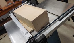
The cabinet was built from inexpensive “birch plywood” from Home Depot, labeled as made in Indonesia. I did not want to eat into my limited supply of Baltic birch, and I thought I would give this product a try. The plywood had some voids which had to be filled on the edges. It did not cut, machine, or sand as nicely as the Canadian made cabinet grade plywood I get from my hardwood lumber shop. There is no issue with the finished cabinet in terms of performance, but there was more work than necessary in working the material. In hindsight, I would have made the 30 mile trip to the lumber shop and paid $20 more for a sheet of maple or birch faced cabinet grade plywood. From now on I will stick with the Canadian stuff when I can’t get Baltic birch.
As I mentioned earlier, this is a sealed box design. That is my preference, I just prefer the quality of the bass from sealed box designs. It also reflects my own limitations as a designer. I have never been really satisfied with any vented box speaker I have ever built, and I find it very difficult to get the damping level just right so that both the bass and midrange sound correct. I have great respect for designers who can find the right combination of vent location, damping, tuning frequency, etc and arrive at a great 2-way vented box speaker. I am not one of them…

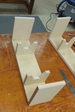
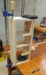
The baffle is double thick. There are three partial bulkhead braces.
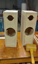
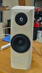
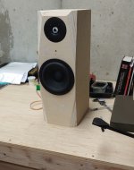
The woofer is positioned at 9 13/16” from the bottom. The tweeter is positioned at 17 13/16” from the bottom. Both drivers are centered. The tweeter is recessed, but the woofer is not. The cabinet is only about ¼” wider than the woofer frame, and I did not think that a recess router cut would be successful with such a narrow edge distance.
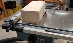
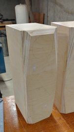
The bevel cuts around the tweeter are at 33 degrees. The tapered bevels on the sides were made on the table saw with a wedge jig I screwed to the back of the cabinet. I selected the taper so that the bevel would begin at the point level with the top of the woofer frame. Around the tweeter, I wanted a ½” edge distance between the bevel and the tweeter recess. So, those two points set the taper angle. When I was cutting the bevel along the top, I screwed up and made the bevel deeper than I intended, so I have only about 1/8” edge distance between the top bevel and the tweeter recess, but fortunately there was no tear out or other problems. The tapered bevels below the woofer are for aesthetics only, they have no affect on the woofer directivity as far as I can tell.
The cabinets were stuffed with long fiber loose wool, well fluffed. I measured out 192 g of wool, which gives me a stuffing density of 16 g/liter, or 16 oz/ft^3.
His current speakers are the MTM version of the Paul Carmody Overnight Sensation. He likes these speakers, but when standing at the bench, he feels the tweeter is too low (it is basically aimed at his belly). I also believe that the MTM configuration might be aiming a null at his face when standing close.
I thought that making a new pair for him might be a fun project. He had some specific requirements:
- Maximum width of the cabinet is 7”.
- Tweeter must be at least 17” above the bench.
- No paper drivers due the garage environment which has drastic changes in temperature and humidity
I wanted to use the SB17CAC35 woofer, but they were sold out in North America when I placed the order, so I used the very similar SB17NBAC35. I chose the 8 ohm version for two reasons. First, the Qts of the 8 ohm is more suitable to a sealed box, and second, his garage amp is an older A/V receiver, and he sometimes drives 2 pairs of speakers with it… no sense in burdening the amp with another 4 ohm speaker.
The cabinet was built from inexpensive “birch plywood” from Home Depot, labeled as made in Indonesia. I did not want to eat into my limited supply of Baltic birch, and I thought I would give this product a try. The plywood had some voids which had to be filled on the edges. It did not cut, machine, or sand as nicely as the Canadian made cabinet grade plywood I get from my hardwood lumber shop. There is no issue with the finished cabinet in terms of performance, but there was more work than necessary in working the material. In hindsight, I would have made the 30 mile trip to the lumber shop and paid $20 more for a sheet of maple or birch faced cabinet grade plywood. From now on I will stick with the Canadian stuff when I can’t get Baltic birch.
As I mentioned earlier, this is a sealed box design. That is my preference, I just prefer the quality of the bass from sealed box designs. It also reflects my own limitations as a designer. I have never been really satisfied with any vented box speaker I have ever built, and I find it very difficult to get the damping level just right so that both the bass and midrange sound correct. I have great respect for designers who can find the right combination of vent location, damping, tuning frequency, etc and arrive at a great 2-way vented box speaker. I am not one of them…
The baffle is double thick. There are three partial bulkhead braces.
The woofer is positioned at 9 13/16” from the bottom. The tweeter is positioned at 17 13/16” from the bottom. Both drivers are centered. The tweeter is recessed, but the woofer is not. The cabinet is only about ¼” wider than the woofer frame, and I did not think that a recess router cut would be successful with such a narrow edge distance.
The bevel cuts around the tweeter are at 33 degrees. The tapered bevels on the sides were made on the table saw with a wedge jig I screwed to the back of the cabinet. I selected the taper so that the bevel would begin at the point level with the top of the woofer frame. Around the tweeter, I wanted a ½” edge distance between the bevel and the tweeter recess. So, those two points set the taper angle. When I was cutting the bevel along the top, I screwed up and made the bevel deeper than I intended, so I have only about 1/8” edge distance between the top bevel and the tweeter recess, but fortunately there was no tear out or other problems. The tapered bevels below the woofer are for aesthetics only, they have no affect on the woofer directivity as far as I can tell.
The cabinets were stuffed with long fiber loose wool, well fluffed. I measured out 192 g of wool, which gives me a stuffing density of 16 g/liter, or 16 oz/ft^3.
Attachments
-
 s20230710_151701.jpg522.6 KB · Views: 303
 -
 s20230711_111644.jpg387.8 KB · Views: 272
 -
 s20230717_175045_HDR.jpg373.7 KB · Views: 274
 -
 s20230722_121846.jpg369.9 KB · Views: 261
 -
 s20230722_121853.jpg349.9 KB · Views: 245
 -
 s20230724_191426_HDR.jpg279.2 KB · Views: 319
 -
 s20230726_182728_HDR.jpg268.9 KB · Views: 333
 -
 s20230807_175808.jpg335 KB · Views: 389
 -
 s20230813_143341.jpg387.3 KB · Views: 370

When designing the crossover, I used DATSv3 to measure the impedances, and I scanned the polar responses of both drivers from 0 – 180 degrees in 15 degree increments. I use an Audix TM1 mic, Behringer UMC202HD audio interface, ARTA, and VituixCad. I merged the nearfield and farfield responses using the standard Vcad methodology.
These speakers are going to be sitting on a bench, rather close to the front wall. So I had to make an informed estimate about how much baffle step compensation I would need. I have gotten comfortable with active crossover design, where I can adjust the shape and profile of the BSC to fine degree. With this speaker, the large woofer inductor was my single degree of freedom adjustment, and 2.2 mH seemed to be the best compromise.
The woofer has a quasi-3rd order Linkwitz Riley slope at 2k. There is a notch filter to suppress the 5k-7k cone break up.
The tweeter has a quasi-3rd order Linkwitz Riley slope at 2k. It does not follow the ideal slope that closely, and I spent a fair amount of time fiddling with the simulation to get something that worked well.

The raw tweeter response has a +2 dB elevated response from 5k – 8k. It is diffraction related, but this elevated response is present out to 30 degrees. Often-times a diffraction-related peak should be left alone rather than EQ’d, but I had doubts about this one. I used a notch filter to lower the response in this region and flatten out the on-axis curve. When I built the crossover, I made provisions to listen to the system with and without the notch filter. I preferred it with the notch.
The final response is a compromise between a good listening-window response, a good predicted in-room response (PIR), and a good directivity index. The on-axis response is +/- 1.5 dB from 100 to 16k. The listening window is similarly smooth, and slopes down by -3 dB from 500 to 16k. The PIR follows a -1 dB/octave target slope from 100 to 16k, and is within +/- 1.5 dB of the target. The DI has the characteristic hump in the crossover region, and nearly all non-waveguide 2-ways have this hump. In this case the hump is a modest 1.2 dB hump. The wide spacing of the drivers and the minimal baffle area around the tweeter help make this possible.


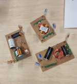
I did not make the cabinet with a removable front or rear baffle, so all crossover parts had to fit into the woofer hole. I made the crossover in three sections to fit on the areas I could access through the hole. I used 1/4” plywood for the crossover boards, and I used Loctite PowerGrab to attach the components to the boards. I soldered the components together on each board, and used lever-lock connectors to wire the boards to each other and to the drivers. I used PowerGrab to glue the boards to the sides/rear baffle.
Loctite PowerGrab is a white latex based construction adhesive with the consistency of thick peanut butter. It has very high initial adhesion, which means for most applications you just press into place. No clamping. Loctite® Power Grab® Heavy Duty (loctiteproducts.com)
I made provisions to adjust the tweeter level by changing out a resistor that can be easily accessed through the woofer hole, and swapped out without soldering. Radj is a resistor in parallel with the 3.3 ohm amp-side series resistor. Radj can be varied from infinite (open) to 2.4 ohm, giving a range of adjustment of 3 dB in tweeter level. 2.4 ohm is +1 dB, 5.6 is +0 (baseline), 12.5 is -1 dB, and open is -2 dB. My preference is 5.6 Ohm.
When I ordered the crossover components from Parts Express, there were some values which were only available as premium brand name (i.e. Jantzen). I did not want to wait, so I placed the order. The crossover parts cost $180 for the pair, and if I could have ordered all Dayton-branded parts, I could have saved about $35. Regardless, the Jantzen parts are very nicely made.
The measured responses of Speaker A and Speaker B both closely match the simulation, which is comforting 🙂


These speakers are going to be sitting on a bench, rather close to the front wall. So I had to make an informed estimate about how much baffle step compensation I would need. I have gotten comfortable with active crossover design, where I can adjust the shape and profile of the BSC to fine degree. With this speaker, the large woofer inductor was my single degree of freedom adjustment, and 2.2 mH seemed to be the best compromise.
The woofer has a quasi-3rd order Linkwitz Riley slope at 2k. There is a notch filter to suppress the 5k-7k cone break up.
The tweeter has a quasi-3rd order Linkwitz Riley slope at 2k. It does not follow the ideal slope that closely, and I spent a fair amount of time fiddling with the simulation to get something that worked well.
The raw tweeter response has a +2 dB elevated response from 5k – 8k. It is diffraction related, but this elevated response is present out to 30 degrees. Often-times a diffraction-related peak should be left alone rather than EQ’d, but I had doubts about this one. I used a notch filter to lower the response in this region and flatten out the on-axis curve. When I built the crossover, I made provisions to listen to the system with and without the notch filter. I preferred it with the notch.
The final response is a compromise between a good listening-window response, a good predicted in-room response (PIR), and a good directivity index. The on-axis response is +/- 1.5 dB from 100 to 16k. The listening window is similarly smooth, and slopes down by -3 dB from 500 to 16k. The PIR follows a -1 dB/octave target slope from 100 to 16k, and is within +/- 1.5 dB of the target. The DI has the characteristic hump in the crossover region, and nearly all non-waveguide 2-ways have this hump. In this case the hump is a modest 1.2 dB hump. The wide spacing of the drivers and the minimal baffle area around the tweeter help make this possible.
I did not make the cabinet with a removable front or rear baffle, so all crossover parts had to fit into the woofer hole. I made the crossover in three sections to fit on the areas I could access through the hole. I used 1/4” plywood for the crossover boards, and I used Loctite PowerGrab to attach the components to the boards. I soldered the components together on each board, and used lever-lock connectors to wire the boards to each other and to the drivers. I used PowerGrab to glue the boards to the sides/rear baffle.
Loctite PowerGrab is a white latex based construction adhesive with the consistency of thick peanut butter. It has very high initial adhesion, which means for most applications you just press into place. No clamping. Loctite® Power Grab® Heavy Duty (loctiteproducts.com)
I made provisions to adjust the tweeter level by changing out a resistor that can be easily accessed through the woofer hole, and swapped out without soldering. Radj is a resistor in parallel with the 3.3 ohm amp-side series resistor. Radj can be varied from infinite (open) to 2.4 ohm, giving a range of adjustment of 3 dB in tweeter level. 2.4 ohm is +1 dB, 5.6 is +0 (baseline), 12.5 is -1 dB, and open is -2 dB. My preference is 5.6 Ohm.
When I ordered the crossover components from Parts Express, there were some values which were only available as premium brand name (i.e. Jantzen). I did not want to wait, so I placed the order. The crossover parts cost $180 for the pair, and if I could have ordered all Dayton-branded parts, I could have saved about $35. Regardless, the Jantzen parts are very nicely made.
The measured responses of Speaker A and Speaker B both closely match the simulation, which is comforting 🙂
Last edited:
No, this is a purely passive design, so I did not do any experiments like that.did you try it with DSP?
One drawback to a sealed box design is that there is no convenient port to get the wires out for testing. When I was fine tuning the crossover, I ran the wires out the back of the speaker through the terminal cup hole. But even when this 3" hole was stuffed with foam, the bass was not right. There was too much air leakage. It was not until I installed the terminal cup and everything was sealed up that the bass came to life.
So if I was going to do DSP experiments, I would have needed some kind of wiring access port.
j.
Did you try listening tests without the notch filter on the SB17NBAC35-8? I used the SB17CAC35-8 and could not hear any difference, let alone an improvement with notch filters. At the time I just assumed that the acoustic LR4 slope of 24db was enough to suppress the breakup. Saved me a few parts which helped in fitting the crossover into a too very small box.
I wish I could say i did, but I did not... Since I orded the parts, I used them.Did you try listening tests without the notch filter on the SB17NBAC35-8?
On some of my earlier active DSP projects using the aluminum cone SB drivers, I measured an improved burst decay / CSD performance when I notched out the cone resonance. I could never be sure if I could hear the difference, but with DSP it was easy enough to mitigate the resonance. So for this passive design, I did the same. I don't think there is a downside to using a notch filter well outside the passband of a driver... Whereas with the tweeter, the notch filter is within the operating range of the tweeter, so I had to evaluate by listening... Does this make sense?
Nice work! Do you hear anything noticeable from the slight peak around ~14 kHz?
My hearing extends to 12k... so no, I hear nothing from the 14k peak 🙂 My wife's hearing still goes to 16k, and she thinks the speakers sound quite good.
One thing that is quite apparent to me is the benefit of a 3-way system with a real woofer. I have used these SB aluminum cone drivers before (SB17CAC35-4, SB15CAC30-4) in active 3-ways, and those systems have better resolution in the upper bass, lower midrange, and even into the upper midrange. My tower speakers I built last year use the same tweeter and very similar midbass driver, but a pair of real woofers handles everything below 300 Hz. https://www.diyaudio.com/community/threads/new-project-tower-3-way-with-twin-8s.378223/post-7142703 The difference in clarity, detail, and resolution in the upper-bass through midrange is very noticeable. I am certain that when these midbass drivers are relieved from the duty of producing 40 - 200 Hz, they become much better at performing as midrange drivers. When this SB17NBAC35 has to make the whole range from 40 - 2k, it does a decent job, but it is just not as good as when it is used as a real midrange driver. I am sure the situation is similar with nearly all of the 5 - 7 inch drivers... with the exception of the magical Purifi... that is a different beast that seems to break the rules...
Overall, I like the sound of these tall thin speakers. Given what they are, they work well, and are very musical and enjoyable. I listened to them yesterday for over 8 hours while I organized my shop and gave it a thorough cleaning.
j.
After listening for a couple of weeks, I concluded that the BSC is close, but it is not quite right. I was noticing an emphasis in the lower midrange. Subjectively it was in the 400 - 800 hz range where I had too much emphasis.
Experimenting with some EQ, I decided I needed to shelve down the response beginning at about 200 Hz, growing to about -1.5 dB shelf by 1000 Hz. In other words, I needed a bit more BSC. My simulation indicated I needed a bit more inductance on the woofer, and then a bit more attenuation on the tweeter to bring it into balance.
This is the baseline crossover:


This is the modified crossover. I added an additional 0.56 mH coil in front of the iron core 2.2 coil. I changed the Radj from 5.6 Ohm to 12.5 Ohm to shelve down the tweeter a bit.

Original response in dashed-blue

The change is noticeable, and the speaker is more relaxed and natural sounding.
Experimenting with some EQ, I decided I needed to shelve down the response beginning at about 200 Hz, growing to about -1.5 dB shelf by 1000 Hz. In other words, I needed a bit more BSC. My simulation indicated I needed a bit more inductance on the woofer, and then a bit more attenuation on the tweeter to bring it into balance.
This is the baseline crossover:
This is the modified crossover. I added an additional 0.56 mH coil in front of the iron core 2.2 coil. I changed the Radj from 5.6 Ohm to 12.5 Ohm to shelve down the tweeter a bit.
Original response in dashed-blue
Uh yeah... Not easy to crossover surgery on the inside of a cabinet through a 5.5" diameter hole... I am very happy that I used lever-lock connectors between the three crossover boards.I did not make the cabinet with a removable front or rear baffle, so all crossover parts had to fit into the woofer hole.
The change is noticeable, and the speaker is more relaxed and natural sounding.
The original plan was to let my brother paint this speaker, but he has a lot going on right now with a major house renovation project. So I decided to finish the speaker.
I decided it would be easier to veneer the cabinet rather than go through all the sanding/filling/sanding prep work to get it ready for paint. I had some cherry veneer left over from another project. I applied 2 coats of polyurethane, sanded with 220, then a third coat of satin polyurethane. I think it looks pretty nice.

I decided it would be easier to veneer the cabinet rather than go through all the sanding/filling/sanding prep work to get it ready for paint. I had some cherry veneer left over from another project. I applied 2 coats of polyurethane, sanded with 220, then a third coat of satin polyurethane. I think it looks pretty nice.
Jim,
Nice work with the veneering and finish, the speakers look classy. Good call on not opting for a paint finish.
Reminds me of Avalon loudspeakers... 🙂
Nice work with the veneering and finish, the speakers look classy. Good call on not opting for a paint finish.
Reminds me of Avalon loudspeakers... 🙂
Looks good and it seems you did a great job on the crossover! Correcting the baffle step compensation is what's often needed after listening to the speaker in it's natural habitat.
One question - why the big distance between tweeter and lf driver? As your brother has a lot of vertical variation I see this as perfect example to put TM as close as possible? Could you show the vertical directivity plot of the simulation? (bottom left curve switched to vertical)
How did you glue the veneer? I have to try this with one of my next projects ... tired of sanding, filling, sanding, filling, sanding, primer, sanding, colour, sanding, colour, sanding ...
One question - why the big distance between tweeter and lf driver?
I have become quite fond of the "Kimmosto Rule" which suggests that driver spacing CtC should be about 1.2 x wavelength of crossover. I have found that when this rule is combined with a minimal baffle area around the tweeter, it is possible to get a smooth DI response... i.e both the on axis response and thee power response can be flat through the crossover. Yes it looks very strange.
How did you glue the veneer?
I use veneer which has a PSA (pressure sensitive adhesive) backing... in other words, peel and stick. I have never had an adhesion failure.
Thanks. There is nothing like a passive crossover to humble you and make you feel like a newbe... I regained my appreciation for the Hypex FA253Looks good and it seems you did a great job on the crossover!
With the wide spacing main lobe gets quite narrow, and additional lobes are introduced above and below making less total destructive interference than very close driver spacing, which is then the smoother DI and power.
Listrning axis sound is fine just like with any spacing, floor/ceiling early reflections might be closer to direct sound due to the added lobes so sound at listening position should be better. Standing up one can hear xo lobe null, but it's not obvious because frequency response dips are tough to hear in general and it's likely one is not at main listening position and listen mostly power and not direct sound, which is now better.
Listrning axis sound is fine just like with any spacing, floor/ceiling early reflections might be closer to direct sound due to the added lobes so sound at listening position should be better. Standing up one can hear xo lobe null, but it's not obvious because frequency response dips are tough to hear in general and it's likely one is not at main listening position and listen mostly power and not direct sound, which is now better.
How did you glue the veneer? I have to try this with one of my next projects ... tired of sanding, filling, sanding, filling, sanding, primer, sanding, colour, sanding, colour, sanding ...
Veneering is very straight forward. My first speaker cabinet built 20 years ago was painted (rear panel) and veneered thanks to Pete Mazz's veneering guide
His step by step process is still as relevant today as it was then. I would reiterate his encouragement to use a good PVA glue- glue (not the generic watery stuff) and let it the glue ‘cure’ for 7 days before use (exposing it to the elements in one of the sunniest places in the world)
These days I don't have time to build cabinets, but if I were to build/finish cabinets, it's worth noting that modern paint processes like automotive 2K, or modern finishes that take 2-3 applications, are excellent. So rather than following traditional processes like shellac and French polish, or even of Danish oil, rubbed and layered with 8 coats, then waxed and buffed to a shine.
Sure, the latter gives a semi-gloss shine and one can still feel the grain, with a silky soft-touch finish.
But it just takes days, if not a week.
Last edited:
Did you consider adding the additional BSC coil on the woofer side to let the woofer 'see' a higher impedance in the mids, and possibly lower the distortion from the woofer?
- Home
- Loudspeakers
- Multi-Way
- Tall Thin 2-way for workshop PC