Another common solution is use of pre-driver to MOSFETS.
This means you add 1 transistor to drive the positive 4 MOSFETS
and one complementary to drive the other 4 'negative'.
This could be a complementary pair MJE15030/MJE15031.
These transistors could use 40-100 mA to drive MOSFETS.
This would take the burdon OFF from Q3.
And you can keep Q3 at 15 mA.
But you then need to increase voltage in VBE multiplier, to set the quiescent current in MOSFET.
Would need to be like 1.5 Volt higher.
This solution would not effect the input stage transistors so much.
They still drive Q3 at 15 mA.
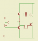
This simple drawing shows
the 2 predrivers that supply all MOSFETs.
Driver transistors can be for example:
BD139/BD140 or MJE15030/MJE150031
You should put these transistors on separate smaller heatsinks.
A couple of Watts need to be cooled.
R1 is resistor that set how much current the predrivers
will use to feed the hungry Gates of those 8 FETs.
Say you get a voltage across R1 = 5V
after you have adjusted quiecent current in FETs.
In this case, If you make R1 = 100 Ohm this will give 50 mA in predrivers.
5V x 0.050 A = 0.25 Watt
So if you R1 is 0.6W rated, it would be okay.
If you put two 47 Ohm in series to make R1 (94 Ohm)
they can take twice as much power.
As you see the voltage to set output MOSFET bias, using trimpot,
will be the two Base-Emitter voltages of predrivers higher than before.
Like 2 x 0.7 volt more.
I think you understood my first post, but was only fun to draw this schematic below!
")
If you should use more or less than 50 mA, I am not sure.
I hope we can get some comment from the more experienced.
the 2 predrivers that supply all MOSFETs.
Driver transistors can be for example:
BD139/BD140 or MJE15030/MJE150031
You should put these transistors on separate smaller heatsinks.
A couple of Watts need to be cooled.
R1 is resistor that set how much current the predrivers
will use to feed the hungry Gates of those 8 FETs.
Say you get a voltage across R1 = 5V
after you have adjusted quiecent current in FETs.
In this case, If you make R1 = 100 Ohm this will give 50 mA in predrivers.
5V x 0.050 A = 0.25 Watt
So if you R1 is 0.6W rated, it would be okay.
If you put two 47 Ohm in series to make R1 (94 Ohm)
they can take twice as much power.
As you see the voltage to set output MOSFET bias, using trimpot,
will be the two Base-Emitter voltages of predrivers higher than before.
Like 2 x 0.7 volt more.
I think you understood my first post, but was only fun to draw this schematic below!
If you should use more or less than 50 mA, I am not sure.
I hope we can get some comment from the more experienced.
Attachments
Hi viktor1986.
I noticed that you split the rails in post #39. This can be a good idea to ensure that Mosfets are fully driven. Problem is you have done it reverse. The voltage available to the input and driver needs to be higher to make up the 3-4 volt gate turn on threshold of the FET. So if tou want 70 volt rails for your outputs then the voltage to your input and driver stage should be 80v
Without this your amp will still work but will clip way below the available rails to the output stage.
Seeya
- Status
- This old topic is closed. If you want to reopen this topic, contact a moderator using the "Report Post" button.
- Home
- Amplifiers
- Solid State
- Take a look on amplifier schematic please