tiroth said:Is the tab voltage 0.3V for both units when disconnected?
You should list the separate disconnected voltages as well as the common connected voltage.
yes, this is the reading from both chips, when they are disconnected. i will see what the voltage it when they are connected.
Matttcattt said:yes, this is the reading from both chips, when they are disconnected. i will see what the voltage it when they are connected.
Hi,
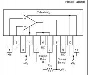
tab (heatsink) voltage on plastic package must be -Ve, metal TO3 is isolated; N.C. What voltage is between two noelectrically connected heatsinks?
Regards
moamps said:
Hi,
tab (heatsink) voltage on plastic package must be -Ve, metal TO3 is isolated; N.C. What voltage is between two noelectrically connected heatsinks?
Regards
both tabs (heatsink) (plastic package) are at 0.3v with the common lead of my multimeter connected to star ground. i do not understand your question. they are both at approx. 0.3v so, no more than 0.1v difference between the heatsinks. have i understood your question correctly?
Matttcattt said:both tabs (heatsink) (plastic package) are at 0.3v with the common lead of my multimeter connected to star ground

What voltage is between pins 3,4 and tab?
What voltage is between 3,4 and stargnd?
Attachments
moamps said:
What voltage is between pins 3,4 and tab?
What voltage is between 3,4 and stargnd?
i cant measure at the moment, but i guess:
A) -14.7v
B) -15v
Matttcattt said:
i cant measure at the moment, but i guess:
A) -14.7v
B) -15v
Strange, according to apps note (A) voltage must be zero....
moamps said:
Strange, according to apps note (A) voltage must be zero....
that is because both are at -Vdc?
millwood said:that is because both are at -Vdc?
Yes,
good readings between some points for PS+/-15V are:
"3,4" - gnd ......-15V
"10,11" - gnd ......+15V
"3,4" - tab ......0V
tab - gnd ......-15V
"10,11" - "3,4" ..... 30V
If IC is directly mounted to the heatsink, then the heatsink must be electrically isolated from all parts inside the chassis and from the chassis itself (if the chassis is metal).
Regards
moamps said:
Yes,
good readings between some points for PS+/-15V are:
"3,4" - gnd ......-15V
"10,11" - gnd ......+15V
"3,4" - tab ......0V
tab - gnd ......-15V
"10,11" - "3,4" ..... 30V
If IC is directly mounted to the heatsink, then the heatsink must be electrically isolated from all parts inside the chassis and from the chassis itself (if the chassis is metal).
Regards
i know this should be true, but both chips tabs are at 0.3v from ground. also, i know that the chips and heatsink should be insulated, and it will be, but i wish to know why the tabs are at 0.3v, and why the two chips will not work when the tabs are electronoically connected.
Hi,Matttcattt said:i know this should be true, but both chips tabs are at 0.3v from ground.
Disconnect amp from power, discharge and desolder PS caps from chip, then measure resistance between "3,4" and tab. If isn't close to zero, than chips are faulty (or apps note is faulty ?!).
Regards
i was trying to measure some resistors with my multimeter and was getting no reading, i found that one of my test leads was broken. i have re-tested the tabs with a new set of (working) test probes, and they are both at -15v as they should be. strangly, both amps still work when the tabs are connected. maybe when i noticed that they didnt work when the tabs were connected was a freak incedent. 
sorry to waste your time.
maybe when i noticed that they didnt work when the tabs were connected was a freak incedent. sorry to waste your time.
- Status
- Not open for further replies.
- Home
- Amplifiers
- Chip Amps
- tabs touching, no output