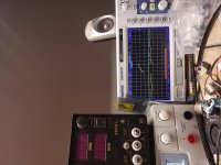
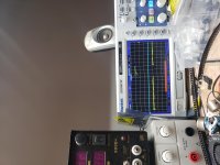
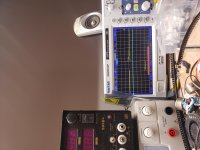
I replaced the driver transistors and diode and gate resistors on all 4 banks. When I check the drive signal 3 banks are at 4.04v and one of them is at 3.75v. The square waves look good and the drive signals coming off of the center leg of the fets of all 4 banks are identical in shape and voltage. When I check the voltage on the rails the +hv rail is at 162vdc but the -hv rail is at 4v. The board is in the heatsink will all screws for testing.
There is only one rail voltage in this amp.
If the rail is fully at the HV+, the amp appears to be in shutdown mode or has lost the connection to the outputs.
Do you see 162v on any of the FETs in the output section? If so, which leg and specifically which FETs?
If the rail is fully at the HV+, the amp appears to be in shutdown mode or has lost the connection to the outputs.
Do you see 162v on any of the FETs in the output section? If so, which leg and specifically which FETs?
What happens if you connect the output stage?
I'm assuming that you only have the red and blue wires disconnected. Is that correct?
I'm assuming that you only have the red and blue wires disconnected. Is that correct?
I've never worked on the output section on one of these amps. I think the power supply is working correctly. I dont know where to start on the output side or what voltages to check for.
There is no electrical connection between the FETs and the MEHSA board/insulator but there are electrical components on some of the MEHSA boards.
I wouldn't connect rail voltage with the FETs off of the heatsink.
I wouldn't connect rail voltage with the FETs off of the heatsink.
Drive waveforms are useless on AC coupling. The waveforms are best taken with the rails disconnected from the output section so you can connect the scope ground to the FET source. Do NOT try that with the rail voltage connected.
Are the outputs in the circuit?
Are the outputs in the circuit?
- Home
- General Interest
- Car Audio
- T30001BD rail voltage


