I don't know the answer, but I know no one wants one when it measures like that on a graph 🙂I don't know how much this effect can be heard at those frequencies.
Is the control at the lower FR range worths this trade off ?

Just arrived:


Next is sanding/smoothing & black painting...
Next is sanding/smoothing & black painting...
One small thing to mention is that it is not good to have the surround come into direct contact with the waveguide. As the surround on the Bliesma drivers is glued to the front plate I print a thin spacer (Donut Ring)of 0.2 to 0.3mm that fits around the outside of the glued surround to stop any pressure being applied.
With my T34A waveguide not using the spacer caused a 4K resonance that went away when the spacer was used.
The same thing can be made from thin card or a couple of layers of tape.
With my T34A waveguide not using the spacer caused a 4K resonance that went away when the spacer was used.
The same thing can be made from thin card or a couple of layers of tape.
Because I am completely noob with fusion or other designing cad software, is there a working stl for t25a waveguide?
I can offer STEP and STL files of the shown WG with the shape as designed by fulid.
Beware:
I've made incoming inspection with a caliper and also measured the T25A and put it roughly, it should fit. Gaps are pretty close; otherwise, no further integration check or measurements were done till now.
M3 threads for the back bracket mounting screws are foreseen to be directly drilled into the body, holes have 2,5mm dia therefore. The print was planned to be from PA12 Nylon that is hopefully solid and strong enough to do so; with softer materials this concept might not work.
Attachments
Can someone please, make the holes disappear?
I used tinker cad, I rotated a mirror waveguide and combine them together, but it left a me artifact which are deep enough to sand them away.
The reason doing so, is that I need to use the waveguide at an already 12cm hole!
I used tinker cad, I rotated a mirror waveguide and combine them together, but it left a me artifact which are deep enough to sand them away.
The reason doing so, is that I need to use the waveguide at an already 12cm hole!
Attachments
Stumbled across the thread and got curious.


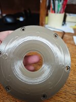
Print was challenging. Unline most models, the 0,16mm HQ preset, which I mostly use, with PLA, which prints very well on my P1S, by far wasn't good enough; in the pictures, you can see my print with the finest & best possible, 0,08mm HQ preset, which turned out much better, but still far from perfect.

I measured it, with the setup pictured above. I won't impose myself, but if someone wants the results, shout and I'll post them.
Print was challenging. Unline most models, the 0,16mm HQ preset, which I mostly use, with PLA, which prints very well on my P1S, by far wasn't good enough; in the pictures, you can see my print with the finest & best possible, 0,08mm HQ preset, which turned out much better, but still far from perfect.
I measured it, with the setup pictured above. I won't impose myself, but if someone wants the results, shout and I'll post them.
No imposition, data is always good to see, it will be different than the simulated situation but still valuable to look at.I measured it, with the setup pictured above. I won't impose myself, but if someone wants the results, shout and I'll post them.
Okay. Beforehand, some more info and context:
The data imported and analyzed in a VituixCAD project:

And I'm also attaching the raw data as .txt / ASCII below:
- print is Kwesi's STL, if that wasn't clear from the pictures
- no spacer was used, so this might influence the results in one way or the other - for you to interprate
- I've used this free air measurement setup before, and it seems to deliver very practical results; see for example this post and the subsequent discussion about the differences to an IEC baffle
- measurement distance was 1m
- the SPL in the measurements was solely chosen for sufficient SNR; meaning these are no 1w/1m sensitivity measurements
- directivity was measured from -180 to +180 degree in 5° steps
The data imported and analyzed in a VituixCAD project:
And I'm also attaching the raw data as .txt / ASCII below:
Attachments
I think these measurements demonstrate that the simulation was accurate. The differences exist in some places due to the waveguide not being mounted in a baffle. The simulated baffle was quite wide and had a large chamfer. The waistband that is seen between 3 and 5K should be less pronounced or gone with a wider baffle and generous rounding. Having the diffraction start right at the edge of the waveguide is not the design intent and in a waveguide as wide as this it will have more effect than in one with a narrower pattern. The diffraction effects are only really apparent in the on axis response which is to be expected in an axisymmetric device. The listening window and 2034 composite curves all follow a smoothly declining trend. Using the 10 degree measurement as the reference axis tends to give a more representative view when there is diffraction in the on axis. There is nothing wrong with choosing 0 degrees as it is a comon reference.
The simulated baffle was quite wide and had a large chamfer.
This one (image attached to the OP)?
Edit: yes - just found the corresponding post in hifijim's thread - https://www.diyaudio.com/community/...way-based-on-bliesma-m74a.420575/post-7903684
I'm not opposed to printing and measuring a version with baffle. I'd also be genuinely curious what the differences to the free air measurements would be. If you don't have the time fluid I can make a model myself based on that picture; though ofc it won't be 100% the same.
Last edited:
I am unlikely to be able to find the time to modify the simulation to be reflective of Kwesi's printable version. If you want to test a similar baffle I can send you the surface model for the baffle to modify into something printable. The only other thing I would consider is how the throat is printing. This is important to get right and can have a negative impact if it is too far from the modeled curve, but I acknowledge this is not always an easy thing to achieve at home with an FDM printer.I'm not opposed to printing and measuring a version with baffle. I'd also be genuinely curious what the differences to the free air measurements would be. If you don't have the time fluid I can make a model myself based on that picture; though ofc it won't be 100% the same.
Yes please.
If print quality was to meaningfully influence the result, I'd expect lack of left-right symmetry in the off axis behavior, since print issues also aren't regular.
If print quality was to meaningfully influence the result, I'd expect lack of left-right symmetry in the off axis behavior, since print issues also aren't regular.
Before proceeding, I tuned the settings again and re-printed the waveguide. I'd say it turned out functionally close to perfect. The differences upon re-measurement in free air to my first print were negligible.
Now, the main point. Fluid sent me the 3D drawing of the baffle he used for the simulation. I created a printable model from it. I had to cut off some of the edges to be able to print it in my P1S (max. corner length 25cm), and I also decided to forego the rear enclosure, as that would have taken up a massive amount of print time and filament, even with thin walls. So, what was measured is not exactly what was simulated, but probably pretty close. I also created a dedicated mount for my turntable to be able to keep reflections off the stand to a minimum:

The results, measured with the same setup and settings as before, again as a VituixCAD import (raw ASCII files attached to this post)

We can observe a major difference to the free air version. I think the explanation is simply that this is a wide radiation waveguide, where edge diffraction will matter a lot. As I alluded to earlier (I can confirm this from one of my projects with an SB Acoustics SB26ADC), and as did Augerpro in the discussion I linked, with his tighter radiation waveguides, the baffle matters less, and the directivity in free air will be very similar to that in a speaker box.
Anyway, that is one beautiful result. There is even beam control down to 1 kHz. If one can replicate that result in a final enclosure, it will make you a very happy DIYer 🙂 (at least IF you're looking for a radiation that wide).
That's it for me. Curiosity satisfied 🙂. I hope my shared data proves useful.
Regards
Stoneeh
Now, the main point. Fluid sent me the 3D drawing of the baffle he used for the simulation. I created a printable model from it. I had to cut off some of the edges to be able to print it in my P1S (max. corner length 25cm), and I also decided to forego the rear enclosure, as that would have taken up a massive amount of print time and filament, even with thin walls. So, what was measured is not exactly what was simulated, but probably pretty close. I also created a dedicated mount for my turntable to be able to keep reflections off the stand to a minimum:
The results, measured with the same setup and settings as before, again as a VituixCAD import (raw ASCII files attached to this post)
We can observe a major difference to the free air version. I think the explanation is simply that this is a wide radiation waveguide, where edge diffraction will matter a lot. As I alluded to earlier (I can confirm this from one of my projects with an SB Acoustics SB26ADC), and as did Augerpro in the discussion I linked, with his tighter radiation waveguides, the baffle matters less, and the directivity in free air will be very similar to that in a speaker box.
Anyway, that is one beautiful result. There is even beam control down to 1 kHz. If one can replicate that result in a final enclosure, it will make you a very happy DIYer 🙂 (at least IF you're looking for a radiation that wide).
That's it for me. Curiosity satisfied 🙂. I hope my shared data proves useful.
Regards
Stoneeh
Attachments
Last edited:
While there was never a doubt in my mind (cough) it is nice to see the visual proof 😎Anyway, that is one beautiful result. There is even beam control down to 1 kHz. If one can replicate that result in a final enclosure, it will make you a very happy DIYer 🙂 (at least IF you're looking for a radiation that wide).
With waveguides this wide everything becomes a source of diffraction in the measurement so I think you have done well to get this close to the prediction. I have to wonder why more manfacturers don't sell their tweeters with these sort of faceplates built in...
WOW - that's a GREAT result for the T25A!
I never liked tweeters with front plate size baffles - it never worked well, no matter what I tried. I made a small test baffle (about 25x35) with huge roundovers and unsymmetric tweeter position, this works very well but of course is not standardised and all and not well comparable to other measurements.We can observe a major difference to the free air version. I think the explanation is simply that this is a wide radiation waveguide, where edge diffraction will matter a lot.
Hi. I know it is not a akabak tutorial thread for beginners but because this is the thread which get my foot in the simulation door... I try.
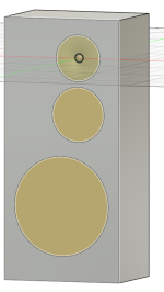
I am considering a big 3 way project (12inch/6inch/bliesma t25b). I subjectively like old school big baffle (see picture 1) but I know it could be suboptimal regarding directivity. I guess that a good simulation can help me evaluating this.
With fusion360, I quickly design the considered design with the thread guidelines for the waveguide + t25b dome profile. I also use fusion360 to export a mesh in STL file (the mesh is clearly not good but my first goal is to validate the process from cad to polar radiation) (see picture 2).
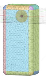
In akabak I import the mesh, create a exterior domain, a mesh element for the wall and a mesh for the driver (see picture 3).
I define my observation (vertical and horizontal polar), click for fixed driving (weight unchanged).
I then ran the calculation but the polar is all red so I miss something but do not know what it is.
Any generous support (or link) will be welcomed 🙏.
I am considering a big 3 way project (12inch/6inch/bliesma t25b). I subjectively like old school big baffle (see picture 1) but I know it could be suboptimal regarding directivity. I guess that a good simulation can help me evaluating this.
With fusion360, I quickly design the considered design with the thread guidelines for the waveguide + t25b dome profile. I also use fusion360 to export a mesh in STL file (the mesh is clearly not good but my first goal is to validate the process from cad to polar radiation) (see picture 2).
In akabak I import the mesh, create a exterior domain, a mesh element for the wall and a mesh for the driver (see picture 3).
I define my observation (vertical and horizontal polar), click for fixed driving (weight unchanged).
I then ran the calculation but the polar is all red so I miss something but do not know what it is.
Any generous support (or link) will be welcomed 🙏.
Attachments

- Home
- Loudspeakers
- Multi-Way
- T25A Simple Waveguide Profile