The calculator calculates the length of the ports, that calculation is one of the determinants as to whether you have selected a suitable driver or not. Onkens typically have 6 - 8 ports and they can be 4 - 5cm wide and 10 - 12 cm tall.
You enter the TS parameters the calculator prompts you for. You also need to enter the source resistance of the device driving the system. (includes amplifier source impedance and the DCR of the inductors in the XO if used)
There is some guidance on the calculator. I will try to do a screen capture of the calculator using my driver as a model when I have some time.
I will try to post a picture of my cabinets as an example of something someone here built and uses on a daily basis. (Coming up on 15 years in a couple of months IIRC)
See if you can find an online copy of the old Jensen Ultraflex booklet, the Onken is a modernized version of that speaker and the booklet is full of useful information and will help you to understand the design a bit better.
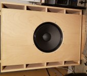
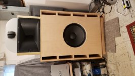
See the attached, it will open correctly despite the sideways orientation. Originally I had intended to use midrange w/lens, and horn tweeter in the cabinet above the woofer. I ended up with much larger midrange horn on top of the cabinet with horn tweeter above that. The center to center spacing is not optimum, I currently cross at 700Hz and have crossed as low as 500Hz but did not like the result.
See the attached, it will open correctly despite the sideways orientation. Originally I had intended to use midrange w/lens, and horn tweeter in the cabinet above the woofer. I ended up with much larger midrange horn on top of the cabinet with horn tweeter above that. The center to center spacing is not optimum, I currently cross at 700Hz and have crossed as low as 500Hz but did not like the result.
Attachments
Thanks Kevin, that helps. I will look for the booklet and play around with port sizes in the calc.
Last edited by a moderator:
Jensen Ultraflex
Attachments
FYI/FWIW: based on heat/AC duct design, the vent ratio needs to be < 9:1 where it starts turning resistive [~aperiodic] enough to audibly roll off the bass, i.e. tunes lower than calculated since IIRC the math doesn't account for it, i.e. shorten the vent's length.
Also, from experience and since proven using MJK's MathCad cab alignment design routines is that the driver offset in a BR, i.e. has a ~uniform particle density, is H*0.42 [i.d.].
That said, IME [and a few others], offsetting the driver to the extreme top in a ~uniform particle density has no audible impact on its response, so not the 'end of the world' 😉 if wanting as close as practical c-t-c spacings.
Thanks for all the info so far and apologies if I seem to have the understanding of a piece of stale bread - a lot of the tech talk is a bit beyond my current knowledge 😕.
Still - I've played around with the calculator linked and have one or two questions - TIA for any explanations (or even an rtfm link 😀 - I'll do my best to utfm)
1) If I fill in my parameters for eight ports, the calc provides for an internal volum of 232l with total port volume of around 12l (244l total). If I change nr of ports to 6 (and keep width/height the same) the calc keeps the internal volume at 232l but reduces port length and total port volume is 6l. In other words, the ratio of portvolume:internalvolume changes quite a bit - surely this can't be right?
2)Rg which is the total resistance - this seems to have a big impact on the design - unexpected for me but I'll accept it. Do you include total resistance of the speaker wire going from amp to speaker? I'm guessing I should...for now I just kept this at the default 1.5
3)What is the difference between effective port length and corrected effective port length? (looks like corrected length is used in calcs and should therrefore be the actual length that I build?)
thx...
- That's correct, but you need to maintain a vent surface area that is = > 85% of the driver SD to meet the Onken/Ultraflex design criteria.
- RG has a big effect as it affects Qes and hence Qts. GM explained this well to me years ago and hopefully will step in as I no longer remember the exact way things work. Raising the Rg can allow a lower box tuning with a given driver as I remember it.
- Corrected effective port length is the build length, I think the area/air column behind the port openings counts as part of the overall theoretical port length.
I'm quite happy with the performance of my Onkens, although there are plenty of other ways to do things. It's pretty important to make sure that the box is properly damped. I found ultimately that 1cm natural animal wool carpet backing applied to the back, one side and the bottom eliminate most out of band radiation through the ports.
Seems like I weekly, if not daily, post this in myriad threads 😉:
[Qts']: [Qts] + any added series resistance [Rs]: Calculate new Qts with Series Resistor
[Rs] = 0.5 ohm minimum for wiring, so may be higher if a super small gauge is used as a series resistor plus any added resistance from an XO/whatever.
edit: If a high output impedance amp [low DF] is used, need to add it in its ohms too [not tap rating].
- That's correct, but you need to maintain a vent surface area that is = > 85% of the driver SD to meet the Onken/Ultraflex design criteria.
- Corrected effective port length is the build length, I think the area/air column behind the port openings counts as part of the overall theoretical port length.
I found ultimately that 1cm natural animal wool carpet backing applied to the back, one side and the bottom eliminate most out of band radiation through the ports.
At this point no longer remember if the articles even gives a percentage other than Thuras's patent Av = Sd, but FWIW when I was doing an Excel SS not knowing about Cyr-Marc's until I went on-line to post it only to find he'd just posted his; the late/lamented JMMLC had graciously translated the articles/vetted mine, listed 75%, but the real goal is per Thiele?/Small? to have a < 4% vent mach [not the current 5%, which IME is achieved with 50%, so personally wouldn't lose any sleep over dipping this low if needed to meet the desired cab shape.
Funny story; me and many/all others that got our primary education studying the pioneer's incredible knowledge base touted the Av = Sd mantra [not to mention published in at least some DIY books/articles] as if to do less was, well, less enough to be an unacceptable compromise for any serious SOTA BR/TL only to find in more recent times an interview published in one of the ATT periodicals? that he only chose it because it kept the math as simple as possible to ensure patent oblique obfuscation!
Correct, with basically the [4] internal walls adding significant end correction combined with the front's, the vent will be much shorter than one 'floating' in the box: https://www.diyaudio.com/forums/att...-dayton-port-length-effective-port-length-jpg
Last edited:
Thanks for all the info so far and apologies if I seem to have the understanding of a piece of stale bread - a lot of the tech talk is a bit beyond my current knowledge 😕.
1)In other words, the ratio of portvolume:internalvolume changes quite a bit - surely this can't be right?
You're welcome!
No problem, not an easy hobby to learn for most folks; I mean I've been actively involved at least to some degree for 65+ years and still learning thanks to the folks on the net and especially here that have the requisite education, computer skills required to continue advancement.
Yes, it's right, but just to clarify; box net volume [Vb] would be 232 L, but the gross volume should in theory be 232 L + gross vent volume + any components/bracing/whatever volume.
- Home
- Loudspeakers
- Full Range
- T/S Parameters for Onken What should I be looking at?