The simplest way I can think of is a mute switch.
Agreed Carlos. But one of the issues that has concerned me is about selling buffered Gainclones to people who may forget to manually mute the output.
I know I could take the stance that if I sell somebody an amp and give them written instructions to mute the output or use speaker protection, then it is not my fault if they damage their speakers.
But I suppose that I am a bit of a perfectionsit and also have a strong conscience, so I am looking for a 'foolproof' protection circuit that will give me peace of mind as well as anybody that I may build a buffered GC for.
Benfica! Well, I guess that you were a happy man then when we 'pinched' Porto's manager (and a couple of their best players)! 😀
Nuuk said:But I suppose that I am a bit of a perfectionsit and also have a strong conscience, so I am looking for a 'foolproof' protection circuit that will give me peace of mind...
Me too.
That was just a suggestion for who wants to do it simple.
I will implement an automatic muting.
Nuuk said:Benfica! Well, I guess that you were a happy man then when we 'pinched' Porto's manager (and a couple of their best players)! 😀
Yes!
Maby this year we win the league.😀
Benfica is the team with more trophys in Portugal by a large margin, although the last 10 years have not been so good.

Oh, Mourinho started as a main coach in Benfica, before going to Porto.
After 3 months of Benfica, without proving anything, Mourinho asked for more money.😱
Benfica let him go, he went to Porto.
The rest of the story you know.
O.K. lets discuss power on delay questions in the tube-buffer thread, as I will do right now.
http://www.diyaudio.com/forums/showthread.php?s=&postid=478071#post478071
Franz
http://www.diyaudio.com/forums/showthread.php?s=&postid=478071#post478071
Franz
Nuuk said:
Agreed Carlos. But one of the issues that has concerned me is about selling buffered Gainclones to people who may forget to manually mute the output.
Exactly!
I think most are familiar with my recommeded use of separate transformer for buffer stage and keeping it On, while switching only the larger power transformer for the output GC stage. Simple manual delay that works 99% (?) of the time.
But what happens if somebody doesn't follow the desired procedure, or simply forgets - or has a power interruption or somesuch.
The following is not a delay, rather a simple technique of damping the the turn-on of the tube buffer stage, a precautionary idea.
An externally hosted image should be here but it was not working when we last tested it.
The added components are shaded in grey and needs to be repeated for both channels (stating the bleeding obvious). The 100uF must be Bi-Polar. The 12K value is only a suggestion, actually the lower the value the greater the effect, but also it must be noted that once cap has charged itself and settled to the same potential as the cathode, then the 12K (or whatever value you use) is in parallel with the load after the coupling cap, in which case above is 22K. These two in parallel combine to load the cathode follower to 7K7.
Does this carry an audible penalty? Don't know, but it shouldn't. Note it won't cause bass roll-off - it's a simple matter if the cathode driver can handle he load, and since the output Z is about 200 Ohm, it should be OK.
Using an actual delay that is not subject to human foibles and failings. able to reset itself, ergo a real delay, then the above should not be necessary.
Joe R.
carlosfm said:
Benfica

Hey, Red & White, the national colours of Denmark, in fact the national team looks like Benfica... and also Man U.
I was maybe hoping Sporting... they got a championship finally after getting Peter Schmeichel in goal... ex Man U... ex Denmark... ex Red & White!
Joe
Joe Rasmussen said:I think most are familiar with my recommeded use of separate transformer for buffer stage and keeping it On, while switching only the larger power transformer for the output GC stage.
You keep the tube always powered?
Joe, on that schematic, with that input impedance, the 3.3uf input cap seams a little high to me.
With a lower cap value you should not have DC (or at least very low DC) on the output of the amp, even at power on.
You may have some noises from the tube at power on, but no DC.
Am I wrong?
PS: I keep calling it valve, and then I go back and write "tube".

You keep the tube always powered?

Joe, on that schematic, with that input impedance, the 3.3uf input cap seams a little high to me.
I offer her my very simple (excuse me) excel sheet to calculate highpass filters...
Download it, and play with it, Carlos!
Franz
P.S.
the calculations are the same, for tubes and valves
Attachments
Franz G said:I offer her my very simple (excuse me) excel sheet to calculate highpass filters...
Her thanks.😀
You have an excel sheet for everything, don't you?
Franz G said:Download it, and play with it, Carlos!
I'm playin' and it doesn't change my mind.
I use 3.3uf with 10k input impedance.
On Joe's schematic there was around 22k input impedance.
I would use a 1.5uf cap.
3.3uf here may not be very effective in removing DC.
IMHO.
My question is, if you are avoiding DC entering the LM3875 with an input cap, why use muting in any form?
Does the valve😀 make too much noises at power on?
World record: one layer
Man, I have an amp with LM4780 on veroboard and you can't imagine the pain it was to make it.
The LM4780 has a really crazy pinout.
Anyway, tonight, nothing to see on TV...
Three hours on PCB Express and I got this.😉
BTW, not finished yet, it's late.
Kevin Haskins said:I could use your input though![/URL]
Man, I have an amp with LM4780 on veroboard and you can't imagine the pain it was to make it.
The LM4780 has a really crazy pinout.
Anyway, tonight, nothing to see on TV...
Three hours on PCB Express and I got this.😉
BTW, not finished yet, it's late.
Attachments
My question is, if you are avoiding DC entering the LM3875 with an input cap, why use muting in any form?
Does the valve make too much noises at power on?
It is a question for the tube/valve buffered thread, Carlos!
On power on, there is a voltage of -35 V at the cathode. As the tube begins to heat, there is a transient from -35V to +0.4V within about 2-3 sec.
As this is a very low frequency with very high amplitude it will be amplified by the chip and appears as (clipped) max. signal at the output (eg DC).
Of course, you could try to filter out this transient by setting the highpass with the coupling cap accurately high. But what happens to your bass reproduction? Too small bypass caps 😉 as you use and too high HPF...
Franz
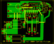
Three hours on PCB Express and I got this.
BTW, not finished yet, it's late.
Very nice, Carlos! I could recognize the t-networks 🙂
And the mute circuit, in the upper right corner. Correct?
Franz
To Franz : I had look at curves of 88 and I mean that in your connection this work with pouintless low current, 'cos Pa is deep bellow Pa max . With higher current you get better linearity and lower distortion 😉 .
Upupa
I remarked the same, and I will soon try higher voltages (+-42VDC) and use a different Rc.
Franz
I remarked the same, and I will soon try higher voltages (+-42VDC) and use a different Rc.
Franz
Franz G said:But what happens to your bass reproduction? Too small bypass caps 😉 as you use and too high HPF...
14Hz is fine for me.😀
Franz G said:Very nice, Carlos! I could recognize the t-networks 🙂
Franz G said:And the mute circuit, in the upper right corner. Correct?
Yes, correct.
I made some small changes after posting it.
Basically I forgot a trace between one of the zobels, and also I changed the line that comes from "SG" resistor to go to exactly the mid point of the small square area (signal ground).
As I was doing the PCB, I lost more time thinking on solutions to keep it single-layer, than actually designing it.
This chip has really crazy pinout.

Not finished yet.
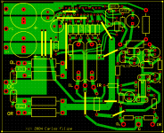
With (optional) op-amp input buffer.
And (optional) bigger PSU caps, as the small ones are for 100uf, for regulated PSU.😎
So... some small changes.😀
BTW, there are already more links than I wanted to, but there's no other way.
Single layer.😎
Not finished yet, but I'm too busy now, I'll finish this soon.
And (optional) bigger PSU caps, as the small ones are for 100uf, for regulated PSU.😎
So... some small changes.😀
BTW, there are already more links than I wanted to, but there's no other way.
Single layer.😎
Not finished yet, but I'm too busy now, I'll finish this soon.
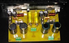
Another IGC .
I finally completed my IGC board. It uses a T network feedback scheme.
The feedback resistor is 100K and the output divider is 2.2K and 75 ohms.
Offset is L ch -18.1mV and R ch +2.1mV. At 68Deg C heatsink temp the offset was L ch -19.6mV and Rch +1.2mV.
Ambinet temp 31deg C. Heatsink temp after 15 minutes ( no signal) was 42 degC . Playing loud music for about 20 minutes with an output of 25 volts peak into 8 ohms speakers ( Mission 701) caused the heat sink temp to rise to 74DegC . That is hot !
My heat sink was 150mm long , 50mm high and with 25 mm long fins ( 20 fins). So I guess a 100 mm tall sink should be fine.
Supply is 4700uF followed by a fuse and then 470uF at the chip . Tracks are not exactly short but it does use star grounding. I think the layout is too big and not very well done. I'll improve on it for the next boad. The large fuse holders are a real pain. I couldn't find any vertical mounting types.
I found that it does sound very clean but harder than my reference amps which are very good . One is a Sherwood and the other a Luxman.
Transients are however very tight and have more bite than my reference amps. Voice unfortunately gets hard as the volume is turned up ,in comparison to the reference. I have not yet connected the tube buffer stage. At high volume and very busy tracks I get a spitting sound which is clearly audible at 60 deg off center from the tweeter. It is HF trash which I should try to look at on an analyser. Voice even at low volume does not come close to what I'm used to from good tubed equipment. If my memory serves me right , the voice doesn't sound as good a Bryston 4B power amp either . I'll have to run in the amp for at least a couple of days to determine how it really sound. The hardness in the voice might reduce or disappear.
Maybe things will change with the buffer also.
I tried a 6922 cathode follower with a CCS and also as a standard gain stage . Both sound good and I found it hard to differentiate between them. If I HAD to choose , I'd pick the cathode follower.
Cheers.
Attachments
Ashok, well done with your amp but I think there are a number of things that you could do to improve the sound.
Using just 1000 uF caps right on the pins and (as you said) using a nice tight star grounding layout, getting rid of the fuses and those electrolytic caps and using a good quality film cap for the input.
But you do have something to build on and make comparsions with so the exercise has been worthwhile. 😉
Hi Nuuk,
Thanks for your suggestions. I was aware of the 'nasty' fuse location. However since there was no other protection , the fuses would do to start with. I can make a fast acting relay to cut off the speakers ( or short the terminals ) in case of DC problems. Contacts in series with the speakers is frowned upon. They however do protect expensive speakers or difficult to get speakers . I have goofed before and I prefer to be on the safe side.
The fuses can come out and probably be on the trafo primary side .
I will try 1000uF at the pins. It might improve the transients further . But I am not sure how the bass would sound. Right now I do get bass but it sounds a bit lean. The -3db point is about 12Hz.
I think there are quite a few things that I can do and I have one reference unit to compare by. It worked out pretty cheap. The most expensive part being the toroidal transformer.
I just tried the cathode follower with the amp. It sounds practically the same . The HF tizziness does not go away. So I will now include an HF filter and see what happens.
I have used a Zobel ( 10 ohms, 0.1uF) and an output inductor wound on a 10 ohm resistor.
On to the next board now and tweaking on the existing board.
Cheers.
By the way those input caps are Jensen Aluminum PIO's. I found them to sound cleaner than the Wima film (MKP10) and other poly prop caps that I have. We've been testing the PIO's against several other caps. Unfortunately the PIO's did sound better especially in the lower level signals. I didn't want it to turn out this way because of their cost. So you might say that we did the test biased against the PIO's! But they won.
- Status
- Not open for further replies.
- Home
- Amplifiers
- Chip Amps
- T-network: the better feedback solution?