people, still kicking tires trying to think of some ideas for a boombox build.
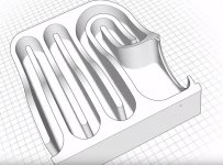
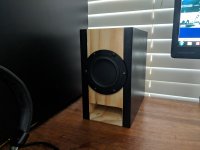
TLines, (or bass reflex) enclosures, how would i look into sizing something like the photo?
This particular one the gentleman used bass box pro and 3d printed an enclosure for a small 3 inch sub, but i was thinking of its application for a small boombox.
i did find some posts from 2010-2014 on here and one had a spreadsheet, but i dont know if it is for the same application.
There was a number of taper selections but 1/11 was what seem to produce the smaller box, but i honestly dont know what that actually represents, it would be great to see a picture of what the internals would be. The required length was about 80cm which seemed ok and the FS around 60hz, which is what i would be chasing from a small 3.5" FR driver.
I've made a small T-Line once before by copying a design on here, but dont know what was done to size it and it had about 2 folds, which not sure if that satisfied anything. It sounded good, but lacked those lower notes.
If there is any direction it would be greatly appreciated, if i can picture something in my head and get some idea into sizing (keeping in mind im a noob, not audiophile) i can start trying to CAD up some options.
Attachments
Only thing i really want out of this, is the smallest enclosure which can provide about a FS of around 60hz and most amount of folds 🙂
I know i can build a 0.17cuft ported box that easily hits 58hz, so now the challenge is something a lot smaller and cooler.
I know i can build a 0.17cuft ported box that easily hits 58hz, so now the challenge is something a lot smaller and cooler.
In which case, build anything you like because your requirements are unfortunately incompatible.
OK, some basics.
-QW / TL enclosures tend to be physically larger for a given LF tuning than, say, a regular vented box.
-A large number of folds is of no benefit in itself, and in many cases (not all) can have a negative impact on performance.
That out of the way, a few more points regarding design.
-A QW / TL, like any other enclosure, needs to be designed for a given drive unit; they form a system, so you can't design a box, stuff any old driver into it, and expect good performance. Unfortunately, it doesn't work that way.
-With the above in mind, a QW / TL variation is not a panacea that allows you to tune lower than the driver is capable of. There's a limit to what can be done, i.e. how far you can go with a quality alignment.
-Tuning frequency of a QW / TL variation is a function of acoustical length; this is a function of physical length and the taper of the line. An expanding line (horn) needs to be physically longer for a given tuning frequency, a contracting line is physically shorter for a given tuning frequency. How much so depends on the degree of taper.
-Folds typically exist simply to pack the desired line into a box with the desired driver & terminus locations, rather than purely for the sake of themselves.
TLines, (or bass reflex) enclosures, how would i look into sizing something like the photo?
There are number of designs that look like that,mostly called horns, that are really a bit of a joke. People like the looks, but that may be their only asset.
dave
Ok, that was just an example as there has been generally some confusion as to what that actually is, ie rear loaded horn, maze, transmission line etc
I guess I used that as a poor example, but thinking the was a straight fold TL. I will take a screen shot of the spreadsheet, but don't really know what a 1/11 taper is, I've heard of 1/4 wave and wondering if there is something lost in translation as I think it may have been a Dutch original.
I guess I used that as a poor example, but thinking the was a straight fold TL. I will take a screen shot of the spreadsheet, but don't really know what a 1/11 taper is, I've heard of 1/4 wave and wondering if there is something lost in translation as I think it may have been a Dutch original.
There's no technical confusion as far as I know, just that there is a lot of misinformation out there.
1:11? Using conventional notation, that would imply an expanding line (horn) with a 1:11 throat - terminus expansion ratio i.e. the terminus has a CSA 11x larger than the throat. Assuming whoever wrote that got it backward, it means a contracting line with an 11:1 taper ratio, i.e. the throat has a CSA 11x greater than the terminus.
1:11? Using conventional notation, that would imply an expanding line (horn) with a 1:11 throat - terminus expansion ratio i.e. the terminus has a CSA 11x larger than the throat. Assuming whoever wrote that got it backward, it means a contracting line with an 11:1 taper ratio, i.e. the throat has a CSA 11x greater than the terminus.
What would this be? I thought it was a TL.
A poor one likely, certainly not anywhere near being optimal. Likely too small and doesn’t take advantage of driver offset.
dave
Here, some background: If the TL was designed using classic techniques it will VERY likely be underperforming. So that you know what to look for to avoid here is a good description of classic design methodology.
Classic TL Design -- Jon Risch
dave
Classic TL Design -- Jon Risch
dave
eough guess of a 6.5 woofer in an undamped line as the nice sktech vs reflex of about the same volume. For the given bulk, that line is tuned higher. Its pipe harmoncs could be tamed with damping material but will lose bass.

What would this be? I thought it was a TL.
Technically ducted port since they have well defined low pass filter chambers and constant area 'vent', so can be designed using a basic reflex calculator such as is one of many types of alignments in Hornresp.
If it was inverse tapered from the top to the bottom, then it would be a TQWT.
GM
thats a bit of information to digest. I wasnt sure if going any of the horns and TL's would result in a smaller enclosure than a vented for a 3.5in FR driver, but cant honestly see how it would if you are needing quite the length.
I'll give it a good read later today when the kids are asleep and do a concept or two to see if i understand.
I'll give it a good read later today when the kids are asleep and do a concept or two to see if i understand.
Oh ok, makes sense.
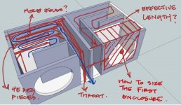
What would this be? I thought it was a TL.
On the assumption that it is,would I need to size the first enclosure? Ps this was called a transmission line for a subwoofer and I have just scribbled on it, so please pardon the mess
The difference in path length, was possibly to not have two ports with interfering output next to each other.
Good idea, bad implementation, and setup is wrong in scope and intent to care about stuff like that.
With such small initial chambers, bass frequencies output, is still going to be directional. You'd want the port out the sides ideally.
For a boombox type setup you'll want regular BR ports, or other restricted tuned vented cabs (aperiodic etc). Or possibly even closed with the right size cab and driver type.
The key word here - at least that's how I see this thread - is "boombox" and that means the rules of the game are different, things like driver sensitivity, driver weight, enclosure weight, enclosure size to low frequency extension ratio are key factors... not to be confused with the way things are done when designing a box to sit/play in a room.
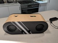
The TL in the attached image in the first post is most likely this one: YouTube - which is neither small nor really that full range, more like a bass heavy tuning, subwoofer type thing... and awfully heavy. Let's go back to the "boombox" rule - the lightest smallest enclosure that can deliver bass should be a closed box with a large passive radiator (and passive radiators can be very light! no need for a steel basket)... which is what the standard commercial portable audio proposes... plus a neodymium driver, smaller magnet means less weight, stronger (neodymium) magnet means more SPL.
Of course this is just engineering for the more likely desired qualities... you can always make is out of pure dinosaur fossil just to make it really really unique.
Actually, I take one look at the image in the first post & 'boom' is about the last thing I would anticipate. Unless the scale is misleading, that's in effect an extremely long, high aspect ratio port (in this sense it wouldn't make much difference whether the chamber was eliminated; the details will change but not the general trend), which will almost certainly result in a low tuning, but very little gain, viz. a highly [over]damped alignment.
Last edited:
the lightest smallest enclosure that can deliver bass should be a closed box with a large passive radiator
If there is a pasive rasiator the box is vented not sealed.
And there are many other factors at play.
dave
If there is a pasive rasiator the box is vented not sealed.
And there are many other factors at play.
dave
I'm not an authority in passive radiator designs but to my knowledge the air inside a passive radiator enclosure is separated (not communicating with the outside) from the outside... my thinking was that it's a lighter version of the sealed enclosure because one of the walls (a portion) is replaced with a passive radiator which is much lighter that the wall it replaces and gives better bass... and my comment was about size/low freq reproduction to weight/size ratio. Also sound quality is secondary to sound quantity in such cases (portable audio).
By the way, if "And there are many other factors at play" you might want to explain you vision of the portable box design philosophy.
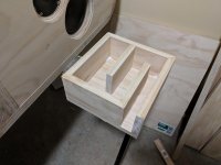
ok, ok, ok, look i always get caught up thinking that maybe i can grab a router and carve me out a maze/labrynth arrangement, or build a proper t line one that actually lets me hit those notes around the mid 50's out of my 3.5inch drivers.
But from what i've been reading outside of this forum, the time you calculate your length required, take into acount wood thickness and the intial chamber, a transmission line may not be as small as i thought. Using an online calculator it would appear that the travel length needs to be around 700mm+ long and i have no idea yet what the inital chamber has to be to cater for 2 drivers.
I'm not too concerned about weight to be honest, just wanted something smaller than my first boombox which ended up being about 450-500mm long. It sounds pretty good for what it is. What got me going with a bit of wood working was the T-Line i just copied from this site, based on the same driver and measurements, it did a nice job, (lacked a little in the lower end), until i lined it up against a vented 0.18cuft enclosure which blew it away (tuned to a FS of 58hz). All to date has used the TEBM65's which i actually like.
On another note, i've researched isobaric, which most information to date only seems to relate to sub woofers and cars, Linkwitz circuits, which look to be only sealed boxes, stuffing the box, which seems to reduce the Q, smaller vented boxes, mazes, bass reflex ports, T lines and honestly completely confused. Most Youtube out there is geared towards subs, where if there is a TLine or maze, it is japanese and listening to classical music, which isnt what i would be listening to.
Just really want to make something smaller (at least 1/2 to 2/3rds the size of the bigger brother), which was tuned to around 60hz, that sounds thumpy when required, not caring if it weighs a kilo.
Attachments
Last edited:
If a goal is to make the smallest possible enclosure, then a TL / QW variation is not the way to go: for a given tuning / alignment they are physically larger than conventional vented boxes. Also, as noted, if you want a one-note 'thump' / 'boom' then a TL is usually also the reverse of what you need, since most such alignments are more highly damped. To a point you can do it, but it's making life more complicated than it actually needs to be. 😉
Note that lambda / 4 only 'works' for untapered lines (and ignores end-correction also); line acoustical length (tuning frequency) is a function of axial length and taper, not length alone.
Note that lambda / 4 only 'works' for untapered lines (and ignores end-correction also); line acoustical length (tuning frequency) is a function of axial length and taper, not length alone.
Last edited:
- Status
- Not open for further replies.
- Home
- Loudspeakers
- Full Range
- T line \ bass reflex enclosure suggestions