You might find Q70 needs a 100pf from collector t obase to stop oscilation on the output. I certainly found that in my quasi amp.
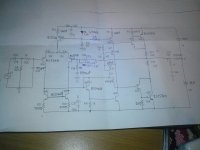
yes its based on d.self's book. i have made this amp and now iam testing it but i am having a problem.
when i power it on ,theres a constant current of 500ma at one rail,regardless the input..
sometimes when i power it on,its ok but after turning up the volume a bit ,theres this constant current of 500ma .
whats this all about?
when i power it on ,theres a constant current of 500ma at one rail,regardless the input..
sometimes when i power it on,its ok but after turning up the volume a bit ,theres this constant current of 500ma .
whats this all about?
yes its based on d.self's book. i have made this amp and now iam testing it but i am having a problem.
when i power it on ,theres a constant current of 500ma at one rail,regardless the input..
sometimes when i power it on,its ok but after turning up the volume a bit ,theres this constant current of 500ma .
whats this all about?
I would strongly suspect some kind of oscillation that triggers on a bit of output power (unless you get DC offset that draws current from one rail only). Once the oscillation starts it might not stop by itself. The amp needs stabilization. These kinds of output stages are prone to oscillation problems, so nothing surprising really. Emitter follower outputs are easier to stabilize, eventhough I haven´t succeeded completely myself in my own design.
Is it oscillating? You will need a scope to find out, because the oscillations could be in the megahertz. Try the caps Nigel sugested.
thanks all for your advice. its the negative rail i have connected the ammeter to,.i dont have a scope unfortunatelly..
dc offset is about 5-6 mV, and bias current is about 25ma.
the sound is ok at the output ,just this problem with the current.
the zobel resistor doesnt get hot .i suspect that when an amp is oscillating ,it drains alot of current but in my case its just 500-600ma
dc offset is about 5-6 mV, and bias current is about 25ma.
the sound is ok at the output ,just this problem with the current.
the zobel resistor doesnt get hot .i suspect that when an amp is oscillating ,it drains alot of current but in my case its just 500-600ma
Unfortunately you will not get very far in finding out what happens without a scope.
Try reducing R41 in steps down to 220R.
After that, try the folloing:
Try adding in series to Q67 emitter a parallel-circuit of the following three elements (don't leave one out, they're all important):
- a resistor smaller or equal to 68R (in steps, R_max=0.6V/I_q_VAS) in parallel with
- a diode (e.g. 1n4148) (kathode tied to rail anode at emitter of Q67 to prevent the emitter of rising above 0.7V over rail voltage) and also in parallel
- a capacitor of about 470pF to keep the gain on track at HF.
instead of a diode you could also use a transistor as self did in his book for current limiting. (guess that might be even more effective).
Try to measure the voltage over the emitter-Rs (R14 + R17) from emitter to emitter.
Check if there are jumps or hystheresis in the voltage displayed on your voltmeter, while setting the bias (no input signal). If the voltage is zero but the current through Q55,Q68,Q57 and Q70 is not -> pretty sure oscillation.
Last edited:
The PCB layout may also be a factor. Sziklai's are quite sensitive to this.
Your schematic doesnt show any on-PCB power supply decoupling. You will want this. Put some 220-330uF decoupling capacitors on the PCB, near to the output transistors. Bypass with 100nF.
Your schematic doesnt show any on-PCB power supply decoupling. You will want this. Put some 220-330uF decoupling capacitors on the PCB, near to the output transistors. Bypass with 100nF.
You might find Q70 needs a 100pf from collector t obase to stop oscilation on the output. I certainly found that in my quasi amp.
I suggested this earlier if it is oscilating.
Hi,
I agree with jaycee....and what transistors are you using for the 'drivers'.
If in doubt the MJ15030/31 seems to work well in this role, IMO the MJE340/350 as recommended by Self are nearly always unstable in this output stage config. Note the pin out is BCE..not ECB so be careful. I just turned them round in Self's pcb. Also try making R16/18 220 ohm at least until you get it working. This tends to slow the output stage down a tad.
Cheers
----------------------------------------------------------------------------------
striving for the perfect Selfless amplfier....
Sorry missed that info in the first post..no experience of this particular combination
OK... is the high current rail the negative one??
If so put 100p across the cb of the -ve side driver, as suggested above.
OK... is the high current rail the negative one??
If so put 100p across the cb of the -ve side driver, as suggested above.
Please check the R20 (10 ohm) , is it warming?
These blue feedback RC might cause oscillation.
The output stage topology is better using emitter follower, because C5200 pair has enough linearity and emitter follower gives more stability.
These blue feedback RC might cause oscillation.
The output stage topology is better using emitter follower, because C5200 pair has enough linearity and emitter follower gives more stability.
I don't see an output inductor. You could be feeding RF directly into the feedback loop & with no inductor it'll have free access to the whole amp. This might not help stability either 😉
what transistors are more suitable for VAS stage?
2sc4793-2sa1837 or
2sd669a-2sb649a??
2sd669a-2sb649a..
2sc4793-2sa1837 are for use as drivers..
- Status
- Not open for further replies.
- Home
- Amplifiers
- Solid State
- Sziklai power amplifier