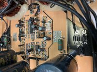
Can’t seem to figure out why both 12 volt regulators are not working on only getting 0.4 volts on the output leg . Black probe on middle leg .
If you need more pics I can take some .
Any ideas ?
If you need more pics I can take some .
Any ideas ?
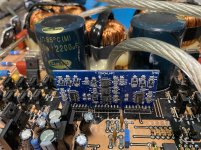
Attachments
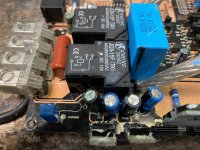
Black probe on middle leg of rectifier for reference or where do I place black probe to see the input voltage ?
With the black probe on the ground terminal of the regulator (middle leg) I get 0.48 volts on the input pin .
On the output pin I get 0.2 volts
On the output pin I get 0.2 volts
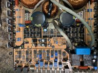
I'd expect the input to be powered by a small secondary winding that goes to 4 diodes. Some use a small secondary that uses a 'doubler' circuit (2 diodes and 2 capacitors).
Follow the input back to see what drives it.
Follow the input back to see what drives it.
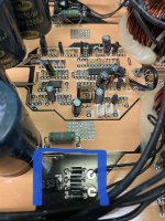
Is that transformer being driven?
Is there any AC voltage across those windings?
Is there any DC voltage across the capacitor?
Is there any AC voltage across those windings?
Is there any DC voltage across the capacitor?
Yes .
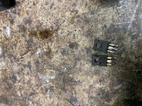
Which I’ve never seen an amp power up and not draw excessive current with the driver transistors shorted
Which I’ve never seen an amp power up and not draw excessive current with the driver transistors shorted
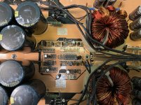
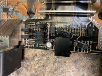
The PNP drivers were shorted so the FET gates were grounded (held off). The NPN drivers are likely open.
Ok that cures that now the regulators are producing 12 volts .
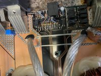
Next question is there was a resistor badly burnt that connects to the negative speaker terminals.
There is another 10k resistor that also connects to the speaker terminals .
Would both of these be 10k do you happen to know ?
Next question is there was a resistor badly burnt that connects to the negative speaker terminals.
There is another 10k resistor that also connects to the speaker terminals .
Would both of these be 10k do you happen to know ?
Attachments

Last edited:
- Home
- General Interest
- Car Audio
- Synergy Audio WTF 7.1D