Hello.
This topic deals with a symmetrically structured pre-regulator, based on inexpensive three-legged regulators.
Assume that you have a floated secondary winding, which does not have direct visibility of the analog ground. The voltage thereof is rectified, filtered, and (hopefully) regulated by means of this concept device of mine.
Here I kindly ask for your analysis, comments and feedback pertaining to the presented circuit. In essence, it is intended to function as a symmetrically structured voltage regulator with symmetrically structured pre-regulators.
My fundamental question: will it oscillate, or will it not oscillate? We are dealing here with complementary regulators, piggy-backed, a pair that could potentially help each other out, but they can also (a scenario which is equally probable or maybe even more likely) fight against each other, interfere with each other.
I drafted this circuit with the goal of (hopefully) achieving unprecedented Signal to Noise Ratio and very good Regulation characteristics. Alas, I am thin on lab measurement infrastructure so as to verify this in praxis.
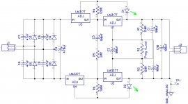
In the context of the basic method of application of a three legged regulator, it seems to me that, assuming an analog ground that is "anchored" to test point TP1:
a). C3 is correctly applied, "by the book", so as to filter out noise from the ADJ pin of the upper, positive regulator.
b). The three legged regulators strive to maintain 1,25Volts on each of the resistors R1 and R3, In this context, any and all "surplus" output voltage, in excess and above 1.25 + 1.25 = 2.5 Volts, need be dropped upon the resistor R2.
c). In the context of b)., and the voltage drop on resistor R2, the use of a parallel connected capacitor C2 seems to me logical, correct and reasonable.
Voltages on R1 and R3 are anchored and "fixed" to 1.25V each, so any noise fluctuations would seem to appear on R2. Connecting C2 in parallel to R2 would seem to filter out any noise upon R2, hence improving circuits output Signal to Noise ratio and its regulation performance. Moreover, I have that gut feeling that this C2 capacitor may have a role to play in terms of killing any parasitic oscillations, but of this - I am not sure. Question to you on this issue.
d). Now comes the big question, pertaining C1: Should it be implemented within this circuit, or discarded? Left out? Does it make sense to "filter out" voltage fluctuations from the ADJ pin of the negative regulator and shunt such noise into the positive output rail? Mind you, the analog ground is anchored to the minus terminal. IMHO, symmetry would "appreciate" the C1 being there, but then there are some trivial, two-transistor multi-vibrators, with two capacitors. They also look very very symmetrical, ... but they oscillate. Do I beneficially put the C1 into the circuit, or should I rather omit it, as it could be potentially counter-productive ? ....
A word of comment, before your comments. Please kindly have a look at the intriguing figure: "Signal / Noise better or equal to 100dB". This information you shall find in the last paragraph, a comment to the last picture, on this following web page:
Using 3-pin regulators off-piste: part 4
Asian versions of three-legged LM317 / LM337 are cheap as dirt.
You could also implement a more audiophile like version of such a circuit, based upon original Linear Technology based chips.
But before I embark into doing that, first I would like to determine whether these complementary regulators, biting at each others tails, will they fall into an oscillations schizophrenia, or will they actually be multiplying out their internal gains to reach an even higher level of precision regulation, and better values of S/N ?
And if indeed there is any risk of oscillations, it is appropriate to fight against ity with the use of capacitors C1, C2, C3, or possibly yet others ?
Please kindly comment.
This topic deals with a symmetrically structured pre-regulator, based on inexpensive three-legged regulators.
Assume that you have a floated secondary winding, which does not have direct visibility of the analog ground. The voltage thereof is rectified, filtered, and (hopefully) regulated by means of this concept device of mine.
Here I kindly ask for your analysis, comments and feedback pertaining to the presented circuit. In essence, it is intended to function as a symmetrically structured voltage regulator with symmetrically structured pre-regulators.
My fundamental question: will it oscillate, or will it not oscillate? We are dealing here with complementary regulators, piggy-backed, a pair that could potentially help each other out, but they can also (a scenario which is equally probable or maybe even more likely) fight against each other, interfere with each other.
I drafted this circuit with the goal of (hopefully) achieving unprecedented Signal to Noise Ratio and very good Regulation characteristics. Alas, I am thin on lab measurement infrastructure so as to verify this in praxis.
In the context of the basic method of application of a three legged regulator, it seems to me that, assuming an analog ground that is "anchored" to test point TP1:
a). C3 is correctly applied, "by the book", so as to filter out noise from the ADJ pin of the upper, positive regulator.
b). The three legged regulators strive to maintain 1,25Volts on each of the resistors R1 and R3, In this context, any and all "surplus" output voltage, in excess and above 1.25 + 1.25 = 2.5 Volts, need be dropped upon the resistor R2.
c). In the context of b)., and the voltage drop on resistor R2, the use of a parallel connected capacitor C2 seems to me logical, correct and reasonable.
Voltages on R1 and R3 are anchored and "fixed" to 1.25V each, so any noise fluctuations would seem to appear on R2. Connecting C2 in parallel to R2 would seem to filter out any noise upon R2, hence improving circuits output Signal to Noise ratio and its regulation performance. Moreover, I have that gut feeling that this C2 capacitor may have a role to play in terms of killing any parasitic oscillations, but of this - I am not sure. Question to you on this issue.
d). Now comes the big question, pertaining C1: Should it be implemented within this circuit, or discarded? Left out? Does it make sense to "filter out" voltage fluctuations from the ADJ pin of the negative regulator and shunt such noise into the positive output rail? Mind you, the analog ground is anchored to the minus terminal. IMHO, symmetry would "appreciate" the C1 being there, but then there are some trivial, two-transistor multi-vibrators, with two capacitors. They also look very very symmetrical, ... but they oscillate. Do I beneficially put the C1 into the circuit, or should I rather omit it, as it could be potentially counter-productive ? ....
A word of comment, before your comments. Please kindly have a look at the intriguing figure: "Signal / Noise better or equal to 100dB". This information you shall find in the last paragraph, a comment to the last picture, on this following web page:
Using 3-pin regulators off-piste: part 4
Asian versions of three-legged LM317 / LM337 are cheap as dirt.
You could also implement a more audiophile like version of such a circuit, based upon original Linear Technology based chips.
But before I embark into doing that, first I would like to determine whether these complementary regulators, biting at each others tails, will they fall into an oscillations schizophrenia, or will they actually be multiplying out their internal gains to reach an even higher level of precision regulation, and better values of S/N ?
And if indeed there is any risk of oscillations, it is appropriate to fight against ity with the use of capacitors C1, C2, C3, or possibly yet others ?
Please kindly comment.
...
Attachments
Last edited:
... oh, and B.T.W. for what it is worth, if indeed it is worth anything at all, this circiut is a (C) 2016, by zjj_wwa (of hiend-audio.com), and as such, is free to be used and fiddled around with in the context of DIY and personal use only, specifically for non-commercial applications.
If you have an acute need to use it in a commercial context ... that would be subject to written consent and hence - we would need to talk.
🙂
If you have an acute need to use it in a commercial context ... that would be subject to written consent and hence - we would need to talk.
🙂
Under UK law all charities have to be registered. I am not registered, so I'm not certain it would be legal for me to give free consultancy to a commercial operation.
This advice (c) 2016.
This advice (c) 2016.
I do not understand.Under UK law all charities have to be registered. I am not registered, so I'm not certain it would be legal for me to give free consultancy to a commercial operation.
This advice (c) 2016.
What commercial operation are you talking about ?
I am a natural person.
- Status
- Not open for further replies.