Hi,
Makes it any sense to build a symmetric preamp PSU using 2 positive PSU in series?
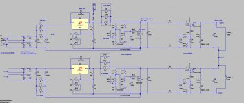
I've build a PSU using one positive and the complementary negative PSU. LM317 + LM337 & IRF510 + IRF9510 cap multiplier. Shunt regulator part is identical.
The issue here is that it needs a lot of tweaking to get output voltages within 100mV the same.
I know the 317 is better than de 337 part. But does the circuit as attached is really better than using a positive and a "real" negative PSU.
Makes it any sense to build a symmetric preamp PSU using 2 positive PSU in series?
I've build a PSU using one positive and the complementary negative PSU. LM317 + LM337 & IRF510 + IRF9510 cap multiplier. Shunt regulator part is identical.
The issue here is that it needs a lot of tweaking to get output voltages within 100mV the same.
I know the 317 is better than de 337 part. But does the circuit as attached is really better than using a positive and a "real" negative PSU.
Attachments
Last edited:
Yes, that's the best way to do it, if you have two isolated secondaries.
A power supply is only positive if its negative terminal is grounded.
If its positive terminal is grounded, then it is a negative power supply.
A power supply is only positive if its negative terminal is grounded.
If its positive terminal is grounded, then it is a negative power supply.
Last edited:
I am confused a little by your question. As shown by this drawing the performance differences of the LM317 and LM337 parts would be 0 at the output of the power supply. Both of these regulators are completely decoupled from the output by the shunt regulator and the cap-multiplier after them.
My guess here is that you are going for the cleanest output you can get. The problem I see is poor overall dynamic regulation caused by the series resistance of all the pass elements. For a fixed current this would be very clean no doubt but for a load that changes while amplifying audio it would have a poor output impedance and be modulated by that load.
Cap-multipliers are good filters but have marginal output impedance at best and are not very good at dynamic loads. Shunt regulators can have similar problems depending on the load. Then add to that the extra heat and wasted power.
If you are simulating this setup I would suggest testing with a dynamic load to see what you really have. That can be as simple as changing the value of the load resistor and see how much the output voltage changes. (try changing the load resistor values by +/-20%) My 50 years of building power supplies tells me that a simple 317-337 supply will overall perform better with a real world load. Now you could put a cap-multiplier ahead of the 317-337 regulators and get more isolation from power-line noise without hurting the output regulation. (The +and - voltage values are easy to trim by adjusting R-16 and R18 and your done.)
Keep in mind that the shunt regulator in the drawing above sets the output voltage and the cap-multiplier lets that voltage move.
Last edited:
I'm fully aware of what your are explaining.
This PSU is for a Class A Pre-amp. Idle current is +-200mA, current variation on output wil be max 2mA in my system.
This setup is definetely not my creation, but is from one of the most experienced people on this forum. My implementation will not be the same but three regalutors in this sequence is what is used in that specific preamp designed by him.
As the load is 200mA, what is the suggested current through the shunt keeping mentioned parameters in mind. I was thinking something like 50..75mA?
Hi Bensen
If you want to be bothered, take a look at Rod Elliot's version of the capacitor multiplier: by using 2 RC filter circuits on the input to the Gate, you can cut down the hum etc. even further.🙂
You can find it here Capacitance Multiplier Power Supply Filter
Cheers
Mike
If you want to be bothered, take a look at Rod Elliot's version of the capacitor multiplier: by using 2 RC filter circuits on the input to the Gate, you can cut down the hum etc. even further.🙂
You can find it here Capacitance Multiplier Power Supply Filter
Cheers
Mike