I had a quick look at the Leach Low Tim amplifier which uses a similar scheme and came up with this: http://i.imgur.com/Igncz.png
I am not sure that would fix the undefined VAS currents though, what do you think ?
I am not sure that would fix the undefined VAS currents though, what do you think ?
I dont think so, ask Cordell for his scheme, hes is helpful and one of the most knowledgable on the forum.
The current mirrors are the problem. There are two easy fixes...ditch the mirrors for a couple resistors. What is the big advantage of using a mirror in the IPS anyway? In this case it is way more trouble than it's worth, IMO. If you insist on using the current mirrors
 , then you can reference the common mode current of the VAS in a feedback loop to the IPS CCS circuits. I think there are another ways but I would swap mirrors for resistors, get the circuit working and then go from there.
If you insist on using the current mirrors, then you can reference the common mode current of the VAS in a feedback loop to the IPS CCS circuits. I think there are another ways but I would swap mirrors for resistors, get the circuit working and then go from there.I got this idea from one of the threads posted in this thread so it has to work: http://i.imgur.com/X1CSi.png
It shouldent matter if the cascode transistor is of another type, does it ?
Btw heres a video of the prototype running in class B(zero bias) http://www.youtube.com/watch?v=81RNHV9_wN4
It shouldent matter if the cascode transistor is of another type, does it ?
Btw heres a video of the prototype running in class B(zero bias) http://www.youtube.com/watch?v=81RNHV9_wN4
Last edited:
I don't understand how the addition of cascodes in the VAS is going to help, although it may provide other benefits. I get the feeling that you don't really understand the problem. CBS240 is right, the problem is the current mirrors. You know what the current is coming out of those current mirrors, but the voltage at the current mirror output is going to assume whatever value it needs to in order to support that current flow. That value is, to a large degree, determined by the transistor current gains. If you replace that current mirror with a simple resistor, you still know what the current is, but now you also know what the voltage is as well. That's the voltage that determines your VAS current.
Regarding your comment about Leach's Low TIM amp in post #21: Leach does not use a similar scheme. He uses resistor loads in the collector circuits of the IPS. That's the key difference. I can't see that you made any changes other than adding Q14 and Q15 in the VAS chain as Leach does. Those provide over current protection in the VAS, but in normal operation do not affect the circuit at all, at least to a first order approximation.
Last edited:
So your essentially saying this: http://i.imgur.com/1W2Qk.png
Now those 18k resistors can still be constant current sources, no ?
Now those 18k resistors can still be constant current sources, no ?
Turns out all this time i've had the bias transistor wired wrong, no wonder it dident work at all. *bashes his head on a brick wall*
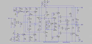
http://i.imgur.com/wcHpN.png <-- this is the final circuit, set to around 25-30mV across 0.44 ohms.
Replacing the current mirrors with resistors does save me the input transistors for a second channel, but im not sure if this circuit is even worth it. I know the instability issue still exist, even though i dont see any oscillations on the scope.
DC offset bounces between 10-25mV on the output with no signal.
Had i discovered the improperly wired bias transistor early on, it would have saved med two IRF540's and two days of headache.
Turned out the lower driver transistors base had been wired to the bias transistors base instead of its emitter, no wonder the bias pot did nothing!!
Guess if i feel stupid now. Feel free to call me a dumb idiot if u want. I feel like getting myself really drunk.
I think you now have a design that will work. There's about 2.8 mA in each of the 15K tail resistors, and hence about 1.4 mA in each collector branch of each LTP. I'm not sure just why you have a 1.5K resistor in series with a 47 ohm resistor, but that combination will result in the collector of Q1 sitting about 2.1 volts below the positive rail, and similarly the collector of Q2 sits about 2.1 volts above the negative rail. Those voltages at the bases of the VAS transistors (Q6 and Q7) will result in a VAS current of (2.1 - Vbe)/300 = ~4.7 mA in the VAS circuit. Note that this calculation is impossible when using the current mirrors.
The reason it's so important that the VAS current be well defined is that otherwise you will find that the upper LTP and the lower LTP will try to drive the VAS current to different values. That imbalance will have to be resolved by the two connections to the IPS, and the result is that the bias spreader will not be centered about zero volts, where it needs to be.
Don't feel too bad about hooking the bias transistor wrong. Everybody who's ever held a soldering iron has done it before. I've hooked up diodes backwards before, so missing a transistor connection is easy to understand. 🙂
Well i feel dumb because i've built this very bias circuit maybe 10 times by now and gotten it right every time or seeing my mistake and correcting it well within 5 minutes, while this one i kept checking and rechecking and just staring at the thing for several hours at a time.
The 47 ohm resistors are in the circuit simply because i was too lazy to remove them, so i just stuck the 1.5k ones in series.
The 47 ohm resistors are in the circuit simply because i was too lazy to remove them, so i just stuck the 1.5k ones in series.
A CCS for R38/39 is OK, it might improve PS rejection. R9/19 & R21/22 should show the same voltage if the LTPs are balanced. When you get it to balance out properly, measure the balance over time and slight variations in temperature to see if it or the VAS common mode current varies much. I find it easier and less likely to have smoke & a pissed-off fit over fried $, if you build the IPS/VAS, then verify that part works and the bias voltages (Vbe multiplier) for the drivers is correct. Then add the drivers, measure & determine voltages/currents are correct. Then add the output stage.😉
Last edited:
On Audio, interesting concept with the CCS also controlling the bases of the VAS transistors.
But what are the diodes for on the IPS collectors ?
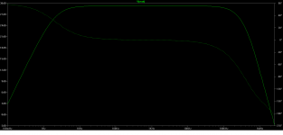
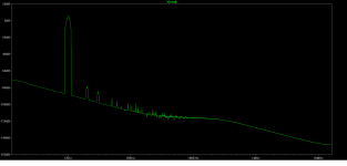
I tried replacing the 15k resistors with CCS's in ltspice but then the circuit turned to crap, THD went way up, from 0.06% with the current mirrors to 0.1% without the current mirrors to 0.5-1% with the CCS's and the frq response started rolling off at 10kHz and phase shift was just horrible.
But what are the diodes for on the IPS collectors ?
I tried replacing the 15k resistors with CCS's in ltspice but then the circuit turned to crap, THD went way up, from 0.06% with the current mirrors to 0.1% without the current mirrors to 0.5-1% with the CCS's and the frq response started rolling off at 10kHz and phase shift was just horrible.
Last edited:
.... ditch the mirrors for resistors, make double vas. figure out a vas bias feedback.The current mirrors are the problem. There are two easy fixes...ditch the mirrors for a couple resistors. What is the big advantage of using a mirror in the IPS anyway? In this case it is way more trouble than it's worth, IMO.
Replace the resistors again vith quad current sorces, and implement two vas stage feedback, 1 common bias, 1 differential bias feedback.
There is not so easy to find a published sheme for this solution.I did a quick search, here are a few threads on the subject:
http://www.diyaudio.com/forums/solid-state/133864-complementary-input-stages-current-mirrors.html
http://www.diyaudio.com/forums/soli...ror-image-topology-construction-troubles.html
http://www.diyaudio.com/forums/soli...one-amp-ie-yet-another-symetric-topology.html
http://www.diyaudio.com/forums/solid-state/16796-unstable-vas-current-amp-slone-book.html
As you can see, it's a problem that's been extensively discussed. I still think Bob Cordell had the best solution, but I couldn't turn it up with the simple search I did. His comments are worth searching for.
Mike
Bob Cordell double current sorce input done "symetric")
Find VAS fighting solution, actually shown in attachement.
Here one wothout optimised values. Make the idea work, then tweak.
Attachments
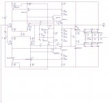
I have now been running this circuit nonstop for around 48 hours straight, and so far it seems stable: http://i.imgur.com/wcHpN.png
Soundwise its nothing special, its kinda generic souding.
Soundwise its nothing special, its kinda generic souding.
- Home
- Amplifiers
- Solid State
- SymiFet A 100% symmetrical mosfet amp