Oooooh.....yes! I have made torture test using 2x 6.5 inches of speaker with a total impedance of 6ohms.mind you again, that the impedance that makes the amplifier put into stress and not the size....:...........
when I said 40v that is D.C. rail supply.
I think that's the same equation I used on the previous page..
So that looks correct to me. 😉
I was under the impression that the Voltage numbers (eg. 30-0-30) are given @ the specified rating (eg. 300VA), and that sometimes idle voltage can be a little higher (to account for resistance in the coil) Vunloaded = Vloaded + I*Rc....................
@ Digger
This is much better Antek - AN-5230. I know someone using +/- 60VDC with 8 ohm load however I like a large safety margin. +/- 40VDC to +/- 50VDC keeps you safe and helps the amplifier drip honey all the way.
Thanks guys!!!
you wind it yourself out of magnet wire.
How about this?
Power Inductors Ind 1uH 3A Radial Leads
or
Power Inductors RFI COIL 1uH 4A
Last edited:
Too small 🙂, not air core. It will saturate easily. This amp is capable of supplying 20A during a transient easy.
Magnet Wire
Magnet Wire, Plain Enamel (PE), Solderable, Class 130, 1 lb spool, 16 AWG CONWIRE-16MAG-1.0LB - All Spectrum Electronics
Amazon.com: Magnet Wire, Enameled Copper Wire, 1lb Spool, 16 AWG, 0.0524" Diameter, 120' Length (Pack of 1): Industrial & Scientific
There are many cheap sources
If pressed disassemble this
http://www.parts-express.com/wizard...CAT&srchCat=281&CFID=3587931&CFTOKEN=90127471
Do for 1uh.(18 turns,16awg-thickness in 1/2" diameter)
Last edited:
Is there a schematic that matches the component layout,to avoid errors.The part numbering of the scheme isn't the same as the board.
Thanks guys.
Next up is to figure out a heatsink size. Does everything on that edge of the board need to attach to the sink and do they all need to be isolated?
This will be my first solid state build. I have done tubes in the past, so this heatsink stuff is all new to me.
Next up is to figure out a heatsink size. Does everything on that edge of the board need to attach to the sink and do they all need to be isolated?
This will be my first solid state build. I have done tubes in the past, so this heatsink stuff is all new to me.
Too small 🙂, not air core. It will saturate easily. This amp is capable of supplying 20A during a transient easy.
20 amp....3200 watt into 8 ohms
 An air-core inductor cannot saturate, else you will be magnetising air.
Last edited:
Too small 🙂, not air core. It will saturate easily. This amp is capable of supplying 20A during a transient easy.
This is given that the speaker has a Z of 4 ohms. And that the PSU is supplying +/-40 V (80V p-p).
U=I*R => I = U/R
Imax = 80V / 4 ohm = 20 A.
Which in turn means:
Pmax = 80 V * 20 A = 1600 W (!!!!!)
At 8 ohm load:
Imax = 80 V / 8 ohm = 10 A
Pmax = 80 V * 10 A = 800 W (!!)
@zxgravediggerxz
So listen to the experts: Use Air-core 😉
Last edited:
According to Mr. Ohm's law P=I^2 x R; therefore P = 20^2 x 8 = 3200 watt, or into 4 Ohms P=1600 watt.
These numbers seems a little Chinese (or Greek as they say) to me. I stand to be corrected, but to store 3200J a 1 Farad Cap is required (since the caps are in series for each 40V rail 200 x 10 000uF caps would do the trick at a cost of around US$1800 at Mouser.)
These numbers seems a little Chinese (or Greek as they say) to me. I stand to be corrected, but to store 3200J a 1 Farad Cap is required (since the caps are in series for each 40V rail 200 x 10 000uF caps would do the trick at a cost of around US$1800 at Mouser.)
According to Mr. Ohm's law P=I^2 x R; therefore P = 20^2 x 8 = 3200 watt, or into 4 Ohms P=1600 watt.
These numbers seems a little Chinese (or Greek as they say) to me. I stand to be corrected, but to store 3200J a 1 Farad Cap is required (since the caps are in series for each 40V rail 200 x 10 000uF caps would do the trick at a cost of around US$1800 at Mouser.)
Your calculations are correct, but with this amp using +/- 40 VDC you will only be able to draw 10 A if you use 8 ohm speakers: 80V (p-p) / 8 ohm = 10 A
But with a +/- 60 V PSU (as suggested in this thread) you can theoretically pull 15 A with an 8 ohm load. That means 15^2*8 = 1800 W (!!!).
To get 3200W out of an 8 ohm load you would need to use +/- 80V PSU. 😉
These numbers are what's called PMPO rating (Peak Momentary Power Output) and describe the maximum instantaneous power possible. A lot of "Chinese" manufacturers use this number to inflate their performance instead of using RMS (Root Means Square) rating which says something about continuous power.
Can other output transistors be used? I bought some OnSemi BJTs in TO-264 packages that are close in specs. I can't remember PN and I'm at work right now.
Re. the comment about air core inductors, I believe OnAudio was misunderstood and he meant to say the ones suggested at Mouser are not air core and will saturate. He is actually recommending air core type.
Re. the comment about air core inductors, I believe OnAudio was misunderstood and he meant to say the ones suggested at Mouser are not air core and will saturate. He is actually recommending air core type.
P = I^2 * R
where I is the DC current.
If you use AC current then you must use Irms for your modeling to be correct.
If you use a sinewave as the test signal and you find it easier to measure an accurate Ipk rather than Irms then that Ipk must be converted back to Irms using the Ipk = Isinewave * sqrt(2).
So back to that 20Apk value.
An 150W into 8ohm capable amplifier will deliver 150W into 8r0 from 49Vpk (=34.6Vac) while meeting a current demand of 6.1Apk (=4.3Aac).
A 8ohm capable amplifier, must be able to deliver at least two times resistive current demand and preferably three to four times that resistive demand from a reactive speaker reproducing fast transients.
That three times the 6.1Apk comes out at 18.3Apk and four times comes out at over 24Apk.
These transients currents are from an 8ohm capable amplifier of just 150W rating, not a 3600W amplifier.
I do wish our Members would start to learn a bit of arithmetic.
Last edited:
I used MJW21195 and MJW21196 instead of 2SC5200 and 2SA1943 with no problems at all.
Tekko, thanks, that is reassuring. IIRC, I have the MJL3281A/MJL1302A sets in my parts bin.
These transients currents are from an 8ohm capable amplifier of just 150W rating, not a 3600W amplifier.
You are correct!
I do wish our Members would start to learn a bit of arithmetic.
Hmmm, can't see anything hugely wrong with the arithmetic so far... 😕
I think we're all on the same page. I was merely trying to demonstrate that huge transients (neighborhood of 20A) is completely possible in this design (@ 4 ohms) and therefore an air-core inductor is the only sensible choice. I was also trying to point out that the "3600W figure" is simply not possible as increased load @ 8ohms effectively halves the Imax at the stated voltage (+/- 40VDC == 80V p-p).
The equations I have provided are all assuming DC voltage (and are "worst-case" scenarios if you like). The 3600W, 1800W and 1500W numbers that are thrown around here (jokingly on my part, I assume the same for everyone else) are merely to demonstrate the maximum impulse power and in no way meant to say anything about the rating of this amplifier (which is somewhere around 150W into 4 ohms).
I hope I haven't confused anyone..
Last edited:
Hi Sondidos,
I am sorry if I misunderstood OnAudio's comment on air-core, maybe all performance related comments are equally nebulous.
In my opinion, if one wants the exact same sound character experienced by others that built and commented on this thread (or any other thread for that matter), the exact same components need to be used as the other constructors did.
So you need to establish who's SYMEF sounded the best out of all the SYMEFs constructed and then use the identical components that was used in the "gold standard" SYMEF, including power components and wiring as well as build quality, etc. else nothing could be verifiably consistent.
But first, establish which is the best sounding SYMEF amongst all the SYMEFs out there - One would do that, maybe by rotating all the amps amongst all the builders with a standard questionnaire until they all agree on the best sounding SYMEF then reproduce that best sounding one faithfully, in every respect. That is more or less how one would do it before going to production, to be able to deliver a consistent product. In a DIY environment like this, unless every componet is characterised and specified, nothing is consistent and all the comments about the "sound" is merely a figment of ones imagination.
Besides you need to also use the identical source equipment, speakers, and probably the same recording to make any sense of it.
Maybe the formula can be used to predict who's SYMEF actually sounds the best by inserting all the variables into the equation and then pressing run.
Last edited:
Is this known scientific fact or just a personal arithmetical preference.
"A 8ohm capable amplifier, must be able to deliver at least two times resistive current demand and preferably three to four times that resistive demand from a reactive speaker reproducing fast transients."
"A 8ohm capable amplifier, must be able to deliver at least two times resistive current demand and preferably three to four times that resistive demand from a reactive speaker reproducing fast transients."
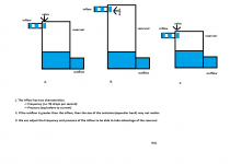
here we go 😀
I guess I will have to take your word how the SYMEF power supply is designed. Could this be the reason that everyone is experiencing the same sound character?
Last edited:
- Home
- Amplifiers
- Solid State
- SYMEF amplifier