Hi still4given,
Amplifiers are often unstable with capacitive loads. The capacitance from speaker output to ground loads the amplifier at high frequencies and reduces the HF feedback. The capacitor will be forced to handle very high currents above 100 KHz somewhere. Whatever frequency the amplifier oscillates at. Many times the amplifier reaches a state where both positive and negative output transistors are both on, causing ridiculously high currents to flow, normally shorting a few. The capacitor can also suffer extreme currents and either short, or burn out a lot of film / foil. There is a network at the output of most amplifiers consisting of an inductor and R-C network. It is very common for the R-C network to burn out, sometimes even the inductor can burn depending on how much current exits to the outside world.
This is a great way to blow up an amplifier by remote, and it represents an unrealistic situation seldom seen in real life (Electrostatic speakers normally). Even stupid speaker wire with a few nF of capacitance can blow up some amplifiers.
This is a dramatic way to show how stable an amplifier is and it is best to work up to the parallel capacitance to see where the amplifier first begins to be unstable. That would be the non-destructive way of testing amplifier stability, also the more intelligent way of doing this. Adding 2 uF across speaker output terminals is very much a torture test in a way. An actual phase margin measurement is all that is needed in the real world.
-Chris
So many to choose from... Given hard driven old speakers with an probale need for short circuit protection - 300W at 4ohm as an minimum at the best specs one can find outta diy community - what would I choose? Modern available components is a must. Do I need to start a new thread or do you think it gathers the essence of the thread?
Regards
Regards
HI Turbon,
The original SymAsym was a 50 wpc deal, but others created variants up into your range for power. Given that you are wondering which amplifier to build, not focusing on the SymAsym, your own thread might be better for you. The information you are asking for is different enough and people might get confused with both requests in the same thread.
-Chris
So many to choose from... Given hard driven old speakers with an probale need for short circuit protection - 300W at 4ohm as an minimum at the best specs one can find outta diy community - what would I choose? Modern available components is a must. Do I need to start a new thread or do you think it gathers the essence of the thread?
Regards
300W !!
You need some omppph ! I only have the small to-3p output transistor slewmaster. (200w/8R - 350w /4R)
http://www.diyaudio.com/forums/solid-state/248105-slewmaster-cfa-vs-vfa-rumble.html
A nice 5-pair MT-200 will do >500W/4R. No "old school" input stages
to drive that kind of power.
- .0005% blameless
- .003% CFA's
- .002% leach amp.
"so many to choose from" - Choose them all ! different forum designs
plug into the power section (below pix).
You could even choose the symasym (with a servo) , all have been tested
at 100's of watts for over 18 months now (start of the slew thread).
OS
Attachments
All tested in real life!300W !!
You need some omppph ! I only have the small to-3p output transistor slewmaster. (200w/8R - 350w /4R)
http://www.diyaudio.com/forums/solid-state/248105-slewmaster-cfa-vs-vfa-rumble.html
A nice 5-pair MT-200 will do >500W/4R. No "old school" input stages
to drive that kind of power.
- .0005% blameless
- .003% CFA's
- .002% leach amp.
"so many to choose from" - Choose them all ! different forum designs
plug into the power section (below pix).
You could even choose the symasym (with a servo) , all have been tested
at 100's of watts for over 18 months now (start of the slew thread).
OS
300W !!
You need some omppph ! I only have the small to-3p output transistor slewmaster. (200w/8R - 350w /4R)
http://www.diyaudio.com/forums/solid-state/248105-slewmaster-cfa-vs-vfa-rumble.html
A nice 5-pair MT-200 will do >500W/4R. No "old school" input stages
to drive that kind of power.
- .0005% blameless
- .003% CFA's
- .002% leach amp.
"so many to choose from" - Choose them all ! different forum designs
plug into the power section (below pix).
You could even choose the symasym (with a servo) , all have been tested
at 100's of watts for over 18 months now (start of the slew thread).
OS
Thanks for the slap 😉
Sure, but as I'm a sucker for protecting my speakers and likewise for circuits for analog meters - does it narrow my search? Heck - if I'll have to pay >1000$ for an McIntosh I rather build one by myself - hopefully with a lot more about information on how it works from input to output. In those 1000$ will be so much knowledge on what sounds best or gives the best outcome for money spent. Not sure the thread is there yet - it will come. If this is the amp to build upon - for the future - say 25 years. Does it have the qualities to be remembered in the audiophile annals as something to better in the future? Just power and thd won't make it in the end I presume. Monoblocks for now with processing power giving alerts when something is outta specs. Of course not disturbing the signal.
Yes, I know - show something yerself - sorry - I just have ideas of what I would like to have... Candy all day long and so on... 🙂
Regards
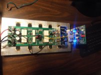
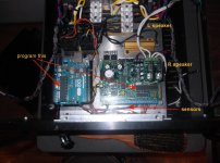
I like my speakers , too. (Below).Sure, but as I'm a sucker for protecting my speakers and likewise for circuits for analog meters - does it narrow my search?
We have all of it covered. AC , overcurrent/rails, DC , thermal , plus the
inrush/softstart - on one small PCB.
Both amp and protection combined ,
what I've shown is more refined than a Macintosh .
Macintosh has fancy , strange layouts and (HUGE) cases ....
I pack 200/350W into a 3U case that is only 325mm deep.
PS - they have many a cheap analog or "magic eye" meter kits on
Ebay. (not that I even like ebay - or their kits).
OS
Attachments
O.k, sorry: not 10kHz but 11kHz!
I have looked at this now.
I refer you to the picture 8R//2uF in your post 10 attachment to the equivalent for http://www.diyaudio.com/forums/solid-state/77562-my-killer-little-amp.html post 7. You can form your own conclusions.
It has been supposed that 8R//2uF is too severe a square wave test load. This raises the question - what happens when the parallel cap is reduced to say 1uF or 0.47uF. Sometimes lower value capacitors give worse results.
Last edited:
My amps would burn the 2uf capacitor to smoke and still run strong !
OS
You should notify your insurer in case your amplifier sets fire to your loudspeakers and house in that order.
I have looked at this now.
I refer you to the picture 8R//2uF in your post 10 attachment to the equivalent for http://www.diyaudio.com/forums/solid-state/77562-my-killer-little-amp.html post 7. You can form your own conclusions.
It has been supposed that 8R//2uF is too severe a square wave test load. This raises the question - what happens when the parallel cap is reduced to say 1uF or 0.47uF. Sometimes lower value capacitors give worse results.
Presumably this trace was without a L//R combination (since the schematic doesn't have it) which, I'm led to believe, can create the ringing shown. FWIW, all my various amp builds over the years have a L//R mounted, so they all exhibit this trait to one degree or another. Oh, and reducing the size of cap invariably improved the ringing.
Brian.
My amps would burn the 2uf capacitor to smoke and still run strong !
OS
I hope you were talking figuratively or in jest - thinking about the question of releasing potentially toxic material into your home enrivonment creating an ongoing health threat needing to be cleaning of carpets, drapes, furnishings, walls ceilings and whatever.
Presumably this trace was without a L//R combination (since the schematic doesn't have it) which, I'm led to believe, can create the ringing shown. FWIW, all my various amp builds over the years have a L//R mounted, so they all exhibit this trait to one degree or another. Oh, and reducing the size of cap invariably improved the ringing.
Brian.
That output coils spoil the square wave output wave form is true, as does a length of connecting speaker cable but you would have to consider the extent to which the result you observe is due to reactance of your L/R and how much is due to loop stability questions.
You say you have experienced this with previous builds to one degree or another. Settling time is a common yardstick in this regard, the shorter the better.
A less stable amplifier will take longer to settle to normal. Looking at the top half of your square wave the ripples persist greatly. If this was due to the L/R you would get rid of it. The more sensible thing would be to improve the stability margin.
Hi alibear,
I built a few SymAsym amplifiers. I originally built one as a utility amplifier knowing it would sound good. Well, it sounds great. I have 6 more boards to build after I am finished some modifications (2SK170 pair for one). Yes, matching pairs of transistors really helps the sound quality out, but this is common to all amplifiers. My original 5.3 builds sound great even now. Do I have stuff that sounds better? Sure I do, but they are more complicated and higher power. I listen to the SymAsym, which was not the intended use when I first built one. For the money and output power, these are hard to beat. This would make an excellent first amp project that will reward you for years to come.
mjona,
People are not having a problem with these amplifiers. There was initially an issue when using different output transistors, but adjusting the compensation fixed that right away. Today there are versions that use all kinds of outputs. It is reasonably forgiving as long as you adjust the compensation if you use different outputs than they were designed with. No surprises there. I used the On-Semi MJW0281A and MJW0302A - excellent. I don't know what bugs you about the SymAsym, but give it a rest. More versions of that amp exist in the world than most any other "community kit" amp, not unless amps designed by ostripper have been more popular, and they may have as I was away for a few years.
-Chris
Have you made changes for MJW0281 and MJW0302?
- Home
- Amplifiers
- Solid State
- Symasym, opinions please.