150w Class AB Audio Power Amplifier Board PCB based on symasym 5-3 | eBay
Has anyone ever bought this and made it?
I would like to buy this board and make it using DC ±55v 500va transformer and njw1302,njw3281 2pair.
Of course, since it is sold as a commercial product, it will work, but it is questionable what quality it will show.
The only difference from the original is 22 ohms and 2.2 ohms. I'm worried if the change is too small.
Attachments
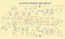
You don't say which resistors you refer to, since there are 6 x 22R and R24A, R24B, R25A, R25B are the same, still 0.22R.
As it is just a PCB, and there are several versions of most Symasym designs, why not follow the Symasym 5-2 design at Michael Bittner's website? (see link below) It can be arranged to use the same 5-3 board by adding wire links in place of R1A, R1B. You can also be sure the designer has built and tested it as you have his article for guidance and description of the performance.
Note that this design is not intended for more than +/- 36VDC power supply. +/- 55V is much too high without modifications and protection circuits as well. You may find that good electrolytic capacitors > 50V, also become too expensive.
SymAsym5 - Project
Last edited:
Sorry. What I mentioned are R1A, R1B, R22 and R23. What I'm curious about is that this version uses high voltage and two parallel output transistors. And there are some changes compared to the original. I was wondering if this would work or if anyone had made it.
Are you saying that the high voltage and 2 parallel to the original symasym can be possible immediately without modification?
And you gave me 5-2 links. Does it have anything special compared to the latest 5-3?
SymAsym5 - Project
Are you saying that the high voltage and 2 parallel to the original symasym can be possible immediately without modification?
And you gave me 5-2 links. Does it have anything special compared to the latest 5-3?
SymAsym5 - Project
5-3 version is not by Michael Bitter - as you see, its a commercial adaptation. You can read Michael's description and comments by others in old threads (about 10 years ago) and more, here at diyAudio if you search the Symasym title via your browser/search engine, such as Google.
+/-45V could be OK as a maximum but you will need substantial heatsinks and watch the component voltage ratings, so no, it needs parts changes and modification to use higher voltages. For example, all electrolytic caps should be rated at least 10% above the nominal working voltage to allow for power variations, surges etc. If you were to use 55VDC rails, you would probably need even more output transistor pairs and high quality, 80V electrolytic capacitors. These are not cheap. The alternative is a properly adjusted protection system which limits current and switches speakers out in the event of overload, shorts and parts failures.
Symasym 5 is a higher power, larger and improved version of the original. There's more to it than even Symasym 4. Look at the schematic diagram of Symasym 5-2, it also has 2 pairs of output transistors and is quite similar to 5-3 but remember, 5-3 is someone else's version - only a few general parts problems associated with kits of 5-3 have been discussed here a few years ago in separate threads.
Obviously, for 5-3, the Symasym design and title have been copied without permission, modified to reduce costs and used for profit by the Chinese seller. In other words, it's a pirated design, modded to avoid trouble but there is little or no support for it.
Resistors R1A,B degenerate the emitters of the long-tailed pair input transistors which is intended to improve linearity. This is not always necessary, depending on the design specifics. Common emitter - Wikipedia
Resistors R22,23 are known as base stoppers, a precaution which inhibits instability (oscillation) when loads are heavy and the operating conditions are poor.
To suggest how something should sound and what affects it, is really the designer's job. Also, opinions of sound quality are strongly influenced by the type of music, recording and playback quality and speakers. I suggest that you build the amplifier as the kit schematic and photos show, listen and decide if it meets your expectations. If not, modify the wiring to follow M. Bittner's Symasym 5-2 and see how that works out. After all, it won't take long to do, the differences aren't all that much and DIY is all about discovering the facts for yourself.
MPSA18 has VCEO of 45v
This design cannot work at more than 40v without changing the input pair MPSA18, they have VCEO of 45v, you need to use the transistors with higher VCEO at least
This design cannot work at more than 40v without changing the input pair MPSA18, they have VCEO of 45v, you need to use the transistors with higher VCEO at least
You are very smart. If it weren't for you, I would have made a big mistake.
Probably 2n5551 is possible, but there may be other problems, so I will give up on this. Thank.
Probably 2n5551 is possible, but there may be other problems, so I will give up on this. Thank.
Hi, Year98.
I did not know that the 5-3 version is not by Michael Bitter. But you`ll find it on his home page. http://www.lf-pro.net/mbittner/Sym5_Webpage/symasym5_3.html
You can also have a look at post #732 in " Symasym 5.3 "AAK model" builder's thread" tread.
If it is of interest,I might have some PCBs laying around at home that I can send to you for the postage. I think it`s the 5-3 version.
Regards
As far as I know, 5-2 and 5-3 are both works of Michael Bittner. And I think the difference between the two is only PCB design.
And thank you very much for your unfortunate suggestion. But I am in South Korea now. This place is too far from Norway. I will appreciate only your heart. Thank.
And thank you very much for your unfortunate suggestion. But I am in South Korea now. This place is too far from Norway. I will appreciate only your heart. Thank.
Last edited:
Note that On Semi MPSA18 is absolete and very hard to come by. There is some other brands of MPSA18. but how they sound compered to On Semi i don't know.
Note that On Semi MPSA18 is absolete and very hard to come by. There is some other brands of MPSA18. but how they sound compered to On Semi i don't know.
Discontinued, that's too sad news.
Any low noise, small signal transistor with a suitable Vceo and Hfe would likely be fine for the input pair. The current popular types here are KSC1845 or the PNP complement, KSA992. Both are also from On Semi and most amplifier designs are now simulated with their models, probably because they are about the best TO92 package transistors available for the application.
Edit:
This link to Bittner 5-3 version seems to work better: SymAsym5 - Project
Edit:
This link to Bittner 5-3 version seems to work better: SymAsym5 - Project
Last edited:
- Home
- Amplifiers
- Solid State
- Symasym 150W at ebay...