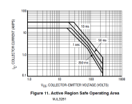
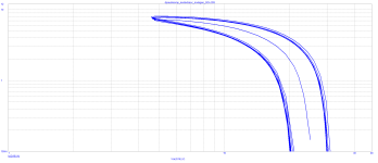
I’ve certainly never blown any of mine. But I’ve seen many many burnt amps using single pairs of 2SC3281/A1302 running off +/-55V. Play them gently with midrange-heavy high crest factor classical they run at 4 ohms all day every day. A few days of boom boom hip hop and there they go - taking the woofers with them.SOA can be reliably simulated with a speaker (Rs + Ls) + ( Rr//Cr//Lr), resonant circuit in series with voice coil parameters. Here the low 2 x 25V and quite robust transistors are an advantage. During the last 20 years, I used more than 100 pairs of MJL3281/1302 and MJL21193/4 and never, never experienced a single failure.
I have now 2 channel modules completed and their parameters are almost identical. I will install them into amplifier case with power supplies and make some more measurements and some listening tests. I will thus reply to the questions later, thank you for understanding.
I don’t even know what it means. Impressive!SOA briefly (simulated speaker complex load, with "back EMF" /I hate that term/):
I hate “back EMF” too, because it is often misinterpreted and misapplied. Back EMF in a motor is an induced voltage opposite in phase to the applied voltage and tends to REDUCE the current draw under light mechanical loading. Speakers draw a lot of current when the motor STALLS (at fb) and back EMF is zero. Just like when you get your drill motor jammed - it heats up PDQ and the lights dim a bit. The magnitude of impedance can still be quite low when the phase angle is large - especially when Qms is high. It’s still not where it reaches its minimum.
The harmonic profile is consistent with mismatched Hfe which seems to be the dominant distortion mechanism, so matching could be one way to improve performance. It is probably not important, although with Hfe mismatch being the dominant distortion mechanism you can expect THD to vary as much from amp to amp as Hfe does from transistor to transistor.
NPN to PNP matching is not always possible, even if you buy 100 each.The harmonic profile is consistent with mismatched Hfe which seems to be the dominant distortion mechanism, so matching could be one way to improve performance.
They just vary from batch to batch.
And you need N to P match to cancel even order harmonics.
Amp to amp variation you can easily keep under control with N to N and P to P match.
In the past, we have had to buy transistors from different sources in the hope to get better N to P match.
Or just accept the higher H2 and H4.
Patrick
Job completed, the amp is in the box. Very low noise, 14uV(A) or 19uV/20Hz-22kHz.

The channels are almost identical, only 0.01dB gain difference.
Some slight induction from the big transformer.


The channels are almost identical, only 0.01dB gain difference.
Some slight induction from the big transformer.
SOA briefly (simulated speaker complex load, with "back EMF" /I hate that term/):
View attachment 1382965 View attachment 1382967
This are the complex impedance plots that were used to simulate SOA (Safe Operating Area, the SOA plots must stay below the datasheet 1s curve, and they do, with a big margin.
Please note the EPDR (Equivalent Peak Dissipation resistance) attacking 2 ohm. The test frequency in the SOA plot was 140Hz.
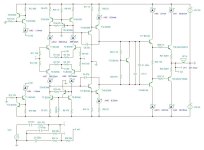
I did some simulation and confirmed that the LTP is actually used only on single arm. That's why the bandwidth is pretty low based on some hand calculation at the back the envelope. I simulated 3 scenarios. Load LTP with resistor on single end; Load LTP with current mirror; Load LTP with your configuration. You can see the current mirror one almost doubles the loop gain bandwidth. Your solution is similar with single end loaded resistor. The difference is minimal. I am sorry to say that it isn't worth your efforts to make one.I suspect the LTP is actually working in one arm. Only half of input current could be used to charge miller cap.
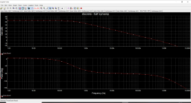
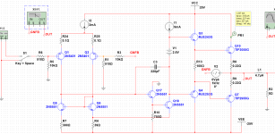
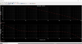
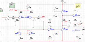
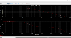
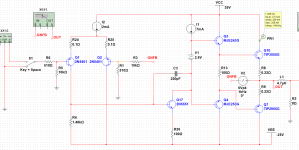
As well-known, LTP at symmetric loading works better. And Pavel knows this because his previous design has more symmetrical load for LTP in first stage. Strange scheme choice
@jxdking , now go on and play with complex load. Put 47nF and then 100nF in parallel with the load resistor and make the stability test again. Which option has higher stability margin? Then make a square wave test and measure the step response with R//C loads. What works better? And finally build those options, test them, make a level matched DBT and tell me again if you hear a difference. It was stated in the post #1, my goal is not to chase inaudible numbers and give the best inaudible distortion with a resistive load. Armchair design is not my goal.
PSRR test of the R loaded option - how did it work?
PSRR test of the R loaded option - how did it work?
Last edited:
20 watts in sim pretty much same thing .01% THD1
That is with perfectly matched sim land transistors.
Second gain stage or Vas Darlington not connected to ground So pretty limiting what is possible.
Dont think the output stage needs 20 watt drivers. Their basically power transistors hard to drive
and need way way more DC bias to be linear. Could just use Bd139/40
Second gain stage is almost 10ma basically does nothing but heat transistors.
Has more current than the drivers. No degen in Diff so wont be very linear
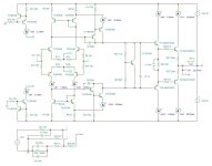

Make a DC stability test with the VAS Darlington connected directly to supply rail in case that one of the input LTP offset voltages changes of 1mV, the realistic scenario. Check the VAS current change, 5x, 10x?. What do you get. BD139/140 drivers - thank you, local stage oscillations, measured on real amplifiers with these parts, are not needed in a DIY amplifier. It is time to take a rest again.Second gain stage or Vas Darlington not connected to ground So pretty limiting what is possible.
Both proposals given in post #33 and #36 lead to DC unstable amplifier. Post #33 simulates one half of the amp only. If enhanced to complementary differential design, a slight change in Vos of one input LTP leads to enormous VAS current change and change of idle current. Similarly the recommendation in post #36 not to use the folded cascode but to tie 2nd VAS transistor emitters to rails leads to the same issue with the VAS current dependence on slight change in Vos, thus the real life amplifier would be useless. Simulators are a great tool but must be used in the whole complexity of operating conditions changes and not only at one single operating point.
Many times indeed.Make a DC stability test with the VAS Darlington connected directly to supply rail in case that one of the input LTP offset voltages changes of 1mV, the realistic scenario. Check the VAS current change, 5x, 10x?. What do you get. BD139/140 drivers - thank you, local stage oscillations, measured on real amplifiers with these parts, are not needed in a DIY amplifier. It is time to take a rest again.
DC is my pet peeve in sim also thermal
Just need helper transistor for mirror and 47k tied across mirror.
DC drops will be equal for 2nd gain stage and mirror with added helper, vas current remains stable.
and fully defined by diff current.
Vas to ground gets rid of a lot of AC feedback issues and THD will spin right down quickly.
- Home
- Amplifiers
- Solid State
- Symamp - simple complementary-symmetrical amplifier (sample built)
