hi Bonasi its nice to see in your site for the below driver transistor for replacement of 1381 and 1302 with same gain grade which is very difficult to get it now.
KSA1220A (this is a PNP)
KSC2690A (NPN)
in replacement for 1381 and 1302
I have just ordered it
Thanks for the input
🙂
Bonsai, can you help me to figure out how to order your PCB set from the approved retailer.
I have tried a few times over the last six months and each time it tells me not available.
I cannot message the retailer since they appear to have turned off messaging.
I tried asking Ebay but got no reply.
I have tried a few times over the last six months and each time it tells me not available.
I cannot message the retailer since they appear to have turned off messaging.
I tried asking Ebay but got no reply.
You do not need to change any resistor values.
Your VBEM allow as much as 20V total VBE, wich mean that the OS quiescent current can be pushed to roughly 25A, the 33R limiting resistor is just cosmetic..
Allowing such max current is not good enginering, and that it sold to 75 exemplaries is not an argument in this matter other than an aknowledgment that the buyers where knowledgeable enough to set the pot at the right end....
Wahab, the instructions are quite clear about setting the pot - they just need to be followed.
Last edited:
100WX2 Ovation NX Current Feedback Amplifier PCB Set New Version 2 0 | eBayBonsai, can you help me to figure out how to order your PCB set from the approved retailer.
I have tried a few times over the last six months and each time it tells me not available.
I cannot message the retailer since they appear to have turned off messaging.
I tried asking Ebay but got no reply.
Unfortunately, this item can't be purchased because the seller isn't accepting bids or offers from you right now.
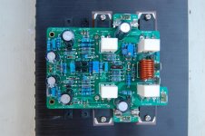
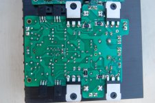
Here is the pictures.. the back side pic is the board with the blown Transistor removed..
I hope to continue debugging later today..
Bonsai, using the 10 Ohm's in the fuse holders - I can safely leave out the fuses? Correct?
I hope to continue debugging later today..
Bonsai, using the 10 Ohm's in the fuse holders - I can safely leave out the fuses? Correct?
Attachments
That's weird, I was able to purchase on my side, just didn't commit to the sale since I already have this amplifier.
Do
AndrewT
I just checked here
100WX2 Ovation NX Current Feedback Amplifier PCB Set New Version 2 0 | eBay
and it seems you can order the items. I note there are 3 offers running - the original which is closed. The link above is to the V2.0 boards. Then there is another link to the V2 boards as well.
Let me talk to the seller to see if we can resolve this - I will try to come back to you in the next day or so.
Last edited:
Here is the pictures.. the back side pic is the board with the blown Transistor removed..
I hope to continue debugging later today..
Bonsai, using the 10 Ohm's in the fuse holders - I can safely leave out the fuses? Correct?
Correct - you can leave the fuses out with the 10 Ohm 5 W resistors in place.
If you do go overcurrent, they will get very hot - but this should prevent you from blowing output devices.
Can you make the readings I asked for earlier and post them so we can try to get this sorted out?
Please check that both the Vbe spreader transistors are ok, the 33 Ohm base stopper resistors are linked out. If you measure wrt 0V either side of the Vbe spreader you should get +1.2V on the collector of Q20 and about -1.2V on the emitter if Q20. If you adjust R6 from maximum down, you should see the voltage across Q20 increase from about half way through the adjustment range.. Can you confirm that the Vbe spreader adjustment resistor is 1k. If you had feor example a 10k in there, the adjustment would be very course - from no output stage bias to far too much and very difficult to adjust it. Is you R6 ok?
I have zero ohms jumpers @ Q12 & Q13 Base
Q12 - base 0V(12mv), collector 51V, emitter -0.6V
Q13 - base -1.2v, collector -51v, emitter -0.62V
Q20 - collector -1.2V, emitter 0.0v
ALL WRT 0
thought I should stop here.
R6 is 1kohm
Can you confirm the Voltge drop across the 0.33 Ohm resistors?
0v taken from emitter of Q1 and emitter of Q2
Suggest while you debug, you insert a 10 Ohm 5W resistor into each of the fuse holders.
11 ohm 10w installed
Ok - if you adjust R6 slowly up, what happens to the voltage across the 0.33 Ohm resistors.
You need to dial it up SLOWLY and then stop when it gets to about 25mV (you must NOT have any load connected at this stage.
You need to dial it up SLOWLY and then stop when it gets to about 25mV (you must NOT have any load connected at this stage.
Ok - if you adjust R6 slowly up, what happens to the voltage across the 0.33 Ohm resistors.
You need to dial it up SLOWLY and then stop when it gets to about 25mV (you must NOT have any load connected at this stage.
I can get in the 25mv neighborhood but it never stabilizes, always drifting up or down.
I think you still have the supply rail resistors in place while trying to bias the output stage.
That will not work properly.
Once you know that the wiring is correct and that the various circuit voltages are as expected, you replace the supply rail fuses and THEN start to bias the output stage. This is when you start measuring the Vre
That will not work properly.
Once you know that the wiring is correct and that the various circuit voltages are as expected, you replace the supply rail fuses and THEN start to bias the output stage. This is when you start measuring the Vre
According to the version 2.09 document (page 13) the normal current from the supply rails at idle is 300 mA. The 11 Ohm resistor should dissipate 1 Watt and drop 3.3 volts. The 10 watt resistor should not get extremely hot nor should it disturb the operating point so much that the bias cannot be at least coarsely adjusted. There appears to be something more wrong with the amplifier. What is the voltage drop across each 11 Ohm 10 watt resistor? Do both channels behave the same way and give the same voltage readings?
Joel is the one trying to bring up his amplifier now. Mine has been working for a long time but yes, I did need to use a light bulb limiter during initial debug. The problem at that time was that the documents indicated that R6 should be set to zero Ohms before power up. That caused a massive over current and blew the rail fuses which prevented any measurements from being made. The light bulb limiter kept the fuses alive and allowed measurements to be made. It became clear that the correct R6 setting was 1K Ohm and the documents were updated.
Nx amp PC boards
Andrew,
I tried to send you a PM but your mailbox is full. If you cannot resolve the issue with ordering the PCBs on ebay, I will order a set and then ship them to you. I recently bought these off ebay and I'm currently building the amp. My boards arrived quickly, only about 8 business days. I would just charge you my cost plus shipping to you. Let me know.
-Richard
Yes AndrewT, I received a similar message from Jims Audio when I tried to purchase the PCBs soon after the Ebay offer was opened. However, there was a distinct suggestion in the email reply after my follow-up query, that I was not the sort of customer they wanted to deal with. I dealt with Jims Audio on 1 prior occasion 4 years ago and gave them their demanded 5 star rating that every Ebay trader insists on. So, I don't know what "Jim's" problem is but they sure don't win any positive votes for snubbing paying customers in that manner......I have tried a few times over the last six months and each time it tells me not available.
I cannot message the retailer since they appear to have turned off messaging.....
I trust they are not singling out members here for our online comments - that would be really childish. It's obvious to me though, that the PCBs need to be pro. manufactured so that leaves some of us high and dry with the project - a great pity.
Last edited:
- Home
- Amplifiers
- Solid State
- SX-Amp and NX-Amp