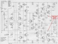
After repairing a SWTPC Tiger .01 (207/A) from the 70's I want to set the bias correctly. I have a copy of the assembly manual and have attached a copy of the schematic and also the bias adjust procedure. However, I question whether the bias procedure is correct. First of all it says that bias current should be set to 40 millivolts. I think they meant to say 40 milliamps. But even if this is what was meant it goes on to say to adjust for 15 mV between test points M and N. Wouldn't that product an idling current of 19.23 mA? If 40mA is the goal, wouldn't the voltage between M & N have to be adjusted to 31.2 mV? Or am I wrong? Thanks for any advice.
Attachments

No point in going over 50mA on those.
I checked the IM distortion on one of mine one time and it was lowest at 10mA!
I checked the IM distortion on one of mine one time and it was lowest at 10mA!
No point in going over 50mA on those.
I checked the IM distortion on one of mine one time and it was lowest at 10mA!
I wish I had an IM distortion analyzer but don't. 🙁
So if I wanted to adjust for 10ma I should measure ~7.8mV between M & N, correct?
Apologize for crashing your thread with no answer but I have two of these amps and no documentation. Do you have the complete manual for these?
I've got quite a bit documentation on the .01's. PM me and I'm sure that I can supply you with what you need.
Here is most of the info that I have on the Tiger .01's, both 207A and 207B..............
https://www.dropbox.com/s/20mfrgowwohvz0y/SWTPC Tiger .01 207A Schematic and Parts List.pdf?dl=0
https://www.dropbox.com/s/ygydpe2y01227nn/SWTPC TIGER .01-207B Schematic and Parts List.pdf?dl=0
Have fun! 🙂
https://www.dropbox.com/s/20mfrgowwohvz0y/SWTPC Tiger .01 207A Schematic and Parts List.pdf?dl=0
https://www.dropbox.com/s/ygydpe2y01227nn/SWTPC TIGER .01-207B Schematic and Parts List.pdf?dl=0
Have fun! 🙂
I recently built a pair of Tigers into an old BGW amp case........... https://www.dropbox.com/sh/ze6tae7kj7bh7c9/AACYL9chzzIQt9V2Mh69lJnTa?dl=0
Last edited:
No point in going over 50mA on those.
I checked the IM distortion on one of mine one time and it was lowest at 10mA!
The power transistor Iq alone would be measured across R39 or R40 whereas the M-N test points include this in combination with driver Iq current.
Does the 50 m.a. limit you mention include the driver stage.
Hi Guys
40mV across the two 380mR sense resistors results in about 53mA total. This is typical for this type of circuit.
Note that the output stage is a CFP with gain, so it essentially has the characteristics described for a CFP in all the audio design books, one of which, is the low idle current required for lowest THD. In these other examples the idle current is that of both the driver and output device since they work as one composite element.
Have fun
Hi Guys
40mV across the two 380mR sense resistors results in about 53mA total. This is typical for this type of circuit.
Note that the output stage is a CFP with gain, so it essentially has the characteristics described for a CFP in all the audio design books, one of which, is the low idle current required for lowest THD. In these other examples the idle current is that of both the driver and output device since they work as one composite element.
Have fun
Thanks for the clarification. It still seems odd that the assembly manual says to adjust for 15mV across the test points. Was this not corrected in later SWTPC documentation?
Hi Guys
A lot of older amps also have a DC offset adjustment. This is set for the lowest mV possible at idle with no signal.
Some bias setting instructions have you set the idle low when the amp is cold. There can be a slight rise as the devices heat up, but to compensate for this a diode or BJT in the bias generator is mounted on the heatsink.
have fun
Hi Guys
A lot of older amps also have a DC offset adjustment. This is set for the lowest mV possible at idle with no signal.
Some bias setting instructions have you set the idle low when the amp is cold. There can be a slight rise as the devices heat up, but to compensate for this a diode or BJT in the bias generator is mounted on the heatsink.
have fun
I work on mostly older amps that usually have a DC offset pot. My Tiger's without them measure 7mV and 9mV which is low enough not to matter. After rebuilding amps I usually monitor both offset and bias while slowly running up the AC using a variac and also watching the AC ammeter for any sudden or unusual current draw. Once when doing this with a B&K amp I noticed that the offset was something like 6 or 8VDC at only about 20 or 30VAC in and thought something was wrong. Checking the other channel I found that it was the same. The thought then occurred to me that the amp used a DC servo for the offset which was controlled by an IC that wasn't operational at this low line voltage. Sure enough, advancing the variac to about 50VAC or so the offset suddenly became 0V and stayed there while line voltage was brought up to 120. I too usually set bias on the low side and wait 5 or 10 minutes and then re-adjust after temp's have stabilized. Of course Tiger's use 1n3754's (D4) for bias tracking which is common in several older amps from that era.
Ercouper,
Still hanging out? Wanted to discuss a couple questions about your 207-A projects.
Thanks,
Mark
Still hanging out? Wanted to discuss a couple questions about your 207-A projects.
Thanks,
Mark
- Home
- Amplifiers
- Solid State
- SWTPC Tiger 207/A bias adjustment