As arm as it should for being biased at 150mA. I didn't measure it. There as a time it got hot due to oscillation but not after I fixed it.
I didn't do the cap shield trick ith Fetzilla, in case you misunderstood.
I didn't do the cap shield trick ith Fetzilla, in case you misunderstood.
Syk,
your FetZilla will run too hot because your heatsink is the wrong shape, the wrong size, in the wrong orientation and is far too thin.
Choose a proper heatsink for the duty !
your FetZilla will run too hot because your heatsink is the wrong shape, the wrong size, in the wrong orientation and is far too thin.
Choose a proper heatsink for the duty !
Syk,
your FetZilla will run too hot because your heatsink is the wrong shape, the wrong size, in the wrong orientation and is far too thin.
Choose a proper heatsink for the duty !
Hi Andrew,
Currently this is the largest heat sink available from the local store here in HK , it measures 12" x 4.5" x 1.25". I will order a set with case after the golden week holiday, will you kindly help to determine what will be the proper type and size ?
Thanks
assume a Ta and Ts for the dissipation you need.
From there you can determine the required Rth s-a to which you have applied the necessary deltaT de-rating.
But you must ensure that your de-rating takes account of the thickness of the backplate. This is not usually specified by the heatsink manufacturer due to the way they all assume isothermal conditions for the entire backplate area.
Mine runs after hours between 38° and 41° and can keeps my hands on the sinks the hole time.
I can touch it butting is quite warm.
Something bad just happened.
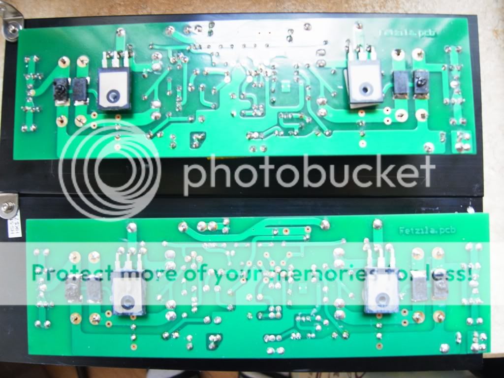

Both channels were working fine on the start-up test before I put them in a temporary case except being a little hot. Today I put them both in a case and connect to a power transformer. After I switch-on the power, a not too loud hum and spark came off from both PCB, it looks like R22 and R24 were blown but everything else looks ok, the fuse still ok. I examine the wiring and discovered that ( I am using only one transformer, a 2 x 26VAC 250VA R-Core) the V+ AC input from left channel and the V- AC input were connecting to the same secondary winding. Could this be the cause to the blown resistors ? What to do next?
Both channels were working fine on the start-up test before I put them in a temporary case except being a little hot. Today I put them both in a case and connect to a power transformer. After I switch-on the power, a not too loud hum and spark came off from both PCB, it looks like R22 and R24 were blown but everything else looks ok, the fuse still ok. I examine the wiring and discovered that ( I am using only one transformer, a 2 x 26VAC 250VA R-Core) the V+ AC input from left channel and the V- AC input were connecting to the same secondary winding. Could this be the cause to the blown resistors ? What to do next?
I intentionally use less solder there so that I can replace those caps easy later on. R22 and R24 will be replaced.
Can anyone help to explain what went wrong with my Fetzilla? the fuse didn't got blown, only R22 and R24. What could be drawing a large current that will cause this? I check at the PCB and cannot locate if there is any component had shortened. What should I check next time when I power it up after replacing R22 and R24?
Thanks
Thanks
Maybe wrong trimmer position during first power-on?
Trimmers were set and check during the initial test before moving to the case.
Were's Hugh?
Haven't seen him for some time now
Do
Hugh has been rather poorly these last few weeks but hopefully on the mend now.
I'm sure I speak for all in wishing him a continued recovery and hopefully we can look forward to seeing him back on the forums.
Can anyone help to explain what went wrong with my Fetzilla? the fuse didn't got blown, only R22 and R24. What could be drawing a large current that will cause this? I check at the PCB and cannot locate if there is any component had shortened. What should I check next time when I power it up after replacing R22 and R24?
Thanks
Hi skylab,
I got the same problem before. You could read my post at:
http://www.diyaudio.com/forums/aksa/207772-fetzilla-build-documentation-8.html
Post #80 onward and see how I discovered the problem
Hi skylab,
I got the same problem before. You could read my post at:
http://www.diyaudio.com/forums/aksa/207772-fetzilla-build-documentation-8.html
Post #80 onward and see how I discovered the problem
Hi ncc,
Thanks for the information ang Hugh had explained it well. I had made the exact mistake when I connect both channel to one transformer, I will replace the resistors and try again this weekend report back.
Thanks for everyone's help.
I'm sorry if this is already made clear somewhere in the previous 101 pages, but I have a simple question about this amp: Is it designed to drive a 4 ohm load? Or can I drive a 4 ohm load when lowering the supply voltage?
Sorry for my laziness, but I didn;t feel like plowing trough 100 pages of replies to find the answer.
Sorry for my laziness, but I didn;t feel like plowing trough 100 pages of replies to find the answer.
- Status
- Not open for further replies.
- Home
- More Vendors...
- AKSA
- Swordfishy/ASPEN FETZILLA power amp