FetZilla BOM
I have a bom from Mouser that I can share but all my resistors I have bought from PartsConnexion (High power are Mills and lower power are Takman metal film) and I have the bom for this one as well.
Mouser
http://www.mouser.com:80/ProjectManager/ProjectDetail.aspx?AccessID=8aed2b3b89
PartsConnexion, see bom.txt attached file
Please don't forget that the quantities are for two boards (stereo) and that I had bought the boards with parts option.
Also, I would change the 1.5uf Polyester caps for Poly type...
As always, double check all parts and qty. Use at your own risk... 😀😀
😀😀
Thanks
Do
Sorry guys to be a non-searching PITA, but did we ever get a final BOM with Mouser or Farnell numbers?
Fran
I have a bom from Mouser that I can share but all my resistors I have bought from PartsConnexion (High power are Mills and lower power are Takman metal film) and I have the bom for this one as well.
Mouser
http://www.mouser.com:80/ProjectManager/ProjectDetail.aspx?AccessID=8aed2b3b89
PartsConnexion, see bom.txt attached file
Please don't forget that the quantities are for two boards (stereo) and that I had bought the boards with parts option.
Also, I would change the 1.5uf Polyester caps for Poly type...
As always, double check all parts and qty. Use at your own risk...
😀😀Thanks
Do
Attachments
Last edited:
I sometimes do a write up on some of the amps that I have built and so I've done one on my Fetzilla which you can see at
http://audioratbag.blogspot.com/2012/02/fetzilla.html
It shows some pictures and some of my thoughts on the sound. I'm not the greatest at construction, but I enjoy it so I suppose that is what really matters.
I really like this amp and I will be taking it to a meet in May in Elkton, Maryland where a group of us DIYers get together and listen to our creations. It will be interesting to hear what the others think
ray
Very nice, Ray! Well made and to the point, agree on amps v. wine in your blog, too.
I tried to comment on your blog, but the profile threw me; didn't have accounts at any of the options unfortunately.
Thanks for giving us your thoughts and showing your work, much appreciated.
Cheers,
Hugh
I tried to comment on your blog, but the profile threw me; didn't have accounts at any of the options unfortunately.
Thanks for giving us your thoughts and showing your work, much appreciated.
Cheers,
Hugh
It's a new blog so I forgot to change the settings to allow comments from anyone. Hopefully it should work now.
ray
ray
Let's make this happen!!!
So far we have the following people
hoxuanduc=2
pinnocchio=3
bbe=2
koldby=4
Total = 11
Ciao!
Do
So far we have the following people
hoxuanduc=2
pinnocchio=3
bbe=2
koldby=4
Total = 11
Ciao!
Do
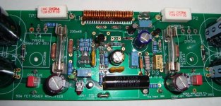
Hello all. This is my first post but I’ve been enjoying the site for a long time and have built a few projects along the way. However, I now need some help with my FETZilla.
These are really nice boards and fun to build (thanks Hugh). I populated one except for the outputs and it powered up OK with ~37V rails and lighted LED’s. I installed the outputs but the bulb tester glows bright. Not good.
Double-checked resistors. Diodes are orientated per drawing and measure OK. Electrolytics are oriented OK. I stuffed the other board to see if I could get one working but it has the same problem. I’m obviously missing something but just don’t see it.
After stumbling around a bit I decided to remove the outputs to help isolate the problem. Tested the power supply with two 75W light bulbs in place of T4 and T5. The rails sag a bit to ~35V with 0.25V P-P ripple so the PS seems OK. I also grounded the output to simulate DC offset = 0. I’m starting to get out of my comfort zone at this point. 🙂
With trim pots at mid-range and input shorted the output gates are –24.5V and –22V. Way too negative. I’ve tried adjusting the trim pots but –2.7V on T5g and 0.9V on T4g is about as good as it gets. If I understand correctly, they should be balanced around zero – yes?
Are the LED voltages OK? Red = 1.74V. Green = 1.92V.
Voltage across R12 = ~ 8V (~3.6mA).
I’m hoping sharper and smarter eyes spot my goof.
Thanks for your time.
John
Attachments
Hi John,
Check these voltages with outputs in.
R8 1K2 Should measure around 3.7V across this resistor.
Voltage across R11 should be around 3-4V.
Voltage across C9 should be around 3.8V.
Offset is adjusted by fiddling P2, the 2K pot across the two leds. Their voltage is fine, BTW.
Check also what current is flowing through R7, 47R. Should have around half a volt across it.
You might clean the flux off the components with white spirit and a toothbrush. Sometimes it can be conductive.
What is the voltage drop across R18 and R17, both 0.1R. Should be around 37-40mV.
Hope this helps,
Hugh
Last edited:
Hello Hugh,
Below are measurements after cleaning the board. I'm using board #2 since it already has the outputs installed and had the same symptoms.
The light bulb tester in series with the primary glows full brightness and my rails are very low at about + / - 3.3V.
Voltage across R8 = 3V.
R11 = 2.5V.
C9 = 1,7V.
R7 = 0.017V (0.4 mA).
R18, 17 = 0.084V and 0.087V (840 mA - 870 mA).
Adjusting the pots has little, if any, effect.
I have a variac if that would help.
Thank again for your time,
John
FetZilla Diagnosis
John,
All measurements point to very little drive on the voltage amp, due to insufficient current through the input stage.
This current is driven by three circuit conditions; an output offset of less than +/-1V, correct value of the fb resistor from output back to the source of the input stage (should be 1K), and adequate voltage at the gate of the input device - should be around +2.5 to +3V.
See what voltage is on the gate of the input device wrt ground.
That should give it away.....
BTW, you can test without the outputs in place if you string the 1K fb resistor from the junction of the first and second diodes on the bias generator (junction of D4 and D5). If you do this, we should be able to get more of an indicator of where the problem lies. I suspect you have put in a wrong value resistor, check (czech!) them all carefully, particularly R8 and R11.
Cheers,
Hugh
Last edited:
Hi,
the very low rail voltage is due to the current limiting of the light bulb tester.
The light bulb tester is used to prevent blowups in the event you have wired somethings wrongly.
The light bulb tester, in it's normal form, cannot be used to bias up the output stage of a power amplifier.
The FetZilla has a very limited range of output bias adjustment.
You cannot use the bulb tester to bias up the output stage of the FetZilla.
Removing the two output devices allows you to check that all else is drawing tiny power.
You can double check the circuit voltages, without the outputs in place.
If you require the "helping hand" of the limiting function of the bulb tester for first power up of the output devices, then you must swap the low power bulb, say 40W or 60W to a higher power bulb. Try 100W, try 150W, try 300W. This is just to prove that the wiring is correct.
Power up direct on line. You may blow the mains fuse. Fit a soft start. Check your soft start using the bulb tester. Once you are happy there are no mistakes, put the bulb tester back on the shelf and finally power up the complete unmodified amplifier. You are ready to set the output bias.
If the FetZilla was more like other power amplifiers, you could simply preset the VR to give near zero output bias and fully test the amp, but FetZilla does not allow that.
Last edited:
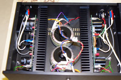
Finally got round to putting my amp in a case and connecting it up to speakers for the first time. Worked straight out the blocks. 😀
It has been playing for a few hours now. Heat sinks are getting toasty warm. Sound is stunning.
I'm feeding it direct from the output of a Buffalo dac. No hum - well OK if you put your ear on the speaker you can hear a very faint buzz in the right channel.
Thanks Hugh
I have built an active crossover recently which I like a lot so can I get another pair of boards?
Group Buy III
Hmmm, C&T, I will have to start up a THIRD Group Buy, dammit!!
I'm delighted you like the sound, the credit is 3/4 Swordfishy, Mikelm and Lineup, tell 'me on the SS forum!!
Credit to you getting through the project, it was worth it, huh?
And yeah, wot Erik says, OK?
Cheers,
Hugh
Hmmm, C&T, I will have to start up a THIRD Group Buy, dammit!!
I'm delighted you like the sound, the credit is 3/4 Swordfishy, Mikelm and Lineup, tell 'me on the SS forum!!
Credit to you getting through the project, it was worth it, huh?
And yeah, wot Erik says, OK?
Cheers,
Hugh
Hmmm, C&T, I will have to start up a THIRD Group Buy, dammit!!
I'm delighted you like the sound, the credit is 3/4 Swordfishy, Mikelm and Lineup, tell 'me on the SS forum!!
Credit to you getting through the project, it was worth it, huh?
And yeah, wot Erik says, OK?
Cheers,
Hugh
Hey Hugh,
I support this idea 110%
I'm a big fan! 😉
Do

No rush for the extra boards.
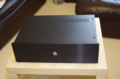
Very nice build! Nice clean look!
BTW, no wonder your heatsinks are getting toasty warm... You should have vents under and on top of the heatsink fins.
You can always do it by yourself or have some custom panels made with Front Panel Design.
Ciao!
Do
Lovely work.
Out of curiosity, how would you make the extra holes in the top and bottom plates so that they looked good.
I'd be out there with the drill making a mess.
I also wonder if your slight buzz in the right channel is because your IEC panel jack is on the right side close to the board.
ray
Out of curiosity, how would you make the extra holes in the top and bottom plates so that they looked good.
I'd be out there with the drill making a mess.
I also wonder if your slight buzz in the right channel is because your IEC panel jack is on the right side close to the board.
ray
- Status
- Not open for further replies.
- Home
- More Vendors...
- AKSA
- Swordfishy/ASPEN FETZILLA power amp