I am working on a OTL headphone amplifier where noise and hum is essential. I can't help being nervous about having AC on my heaters for the 6AS7 output tubes and 6SN7 small signal tubes.
I have done some reading about maybe applying DC to the heaters to eliminate the risk of 50hz noise. I can see that DC on the heaters is not something you do without side effects. My idea however is to mount the heaters in a MOSFET H-bridge so I can switch the current direction with 1Hz or so.
Would this idea give me the best or the worst of both worlds?
For the power supply itself I'm thinking of using a toroid transformer with the heaters in parallel if I go with the pure AC option. If I go for the switched DC I am planning on something like a Mean Well LRS-75-12 with the tubes in series of pairs.
The tubes you use are all indirectly heated and in my experience any "side effects" that might come from dc heating don't apply here. It's a deal wich directly heated tubes.
If you want quiet operation look for something with a floating secondary to be able to elevate the heater potential above cathode potential.
If you want quiet operation look for something with a floating secondary to be able to elevate the heater potential above cathode potential.
New DHT heater, any need for a 10A+ version?
If you really want to go all out with DC heating maybe shoot V4lve Lover a message, it seems mostly intended for directly heated tubes but it will work on indirectly heated tubes for sure.
There is also Rod coleman who has something similar but who operates on a more commercial scale
If you really want to go all out with DC heating maybe shoot V4lve Lover a message, it seems mostly intended for directly heated tubes but it will work on indirectly heated tubes for sure.
There is also Rod coleman who has something similar but who operates on a more commercial scale
I'm a big fan of Coleman regulators on my DHTs but they serve no useful purpose in indirectly heated tubes.
The next question is if I even need the DC? Again my concern is that any noise on the output will go directly to my headphones, so I want to keep the output quiet.
The issue with the DC that I am thinking of is mostly material migration which is said to limit the tube lifespan, but that should be avoided with the H-bridge configuration, and I guess the same goes for any magnetizing of metal components in the heater.
An alternative to the 1hz H bridge would be a set of relays that change the direction of the heater current every time the device is turned on.
I fear you might be overthinking this. I have built in total 3 headphone amplifiers, all of them with AC Heating and they were dead quiet. I have used the ecc88, and 6as7 too with no problems regarding hum
Of course that elevated the heaters to around a fourth of b+.
Of course that elevated the heaters to around a fourth of b+.
Last edited:
If you run the tubes within ( or below) spec, you don't have to be concerned of tube lifetime.
What might be of importance is to keep heater <> cathode close.
What might be of importance is to keep heater <> cathode close.
It's probably best to try AC-heat for these in the first place.
If they are quiet enough, no need to go further.
Some 6SN7 variants have too much hum though. You can fix this with regulated DC or just plain rectified DC.
You do not need to reverse the voltage on indirect heaters - it does not cause any problems at all.
And BTW, Although it causes bias-skewing in directly heated triodes, there are no practical consequences, and the performance is better, given that intermodulation distortion is not present if DC heating is used.
The thing is that I would have to get the power supply for the heaters anyway, so wouldn't the safest bet be a DC supply?
In regard to the heater/cathode voltage, how do I arrange that when my output is a push/pull stage? That would essentially mean that the voltage between cathode and heater will always be different from one triode to the other, within the output tubes.
In regard to the heater/cathode voltage, how do I arrange that when my output is a push/pull stage? That would essentially mean that the voltage between cathode and heater will always be different from one triode to the other, within the output tubes.
The two cathodes of a PP output stage should be near to the same voltage, even with large signals present. It is the grid voltage that swings the big voltage.
You can usually bias the driver heater to ca. 50V or so. Post your schematic, if you need more precise information.
You can usually bias the driver heater to ca. 50V or so. Post your schematic, if you need more precise information.
Tube amp schematic
The thing is, that the PP output is an OTL configuation, so its a totempole configuation where the top tube cathode is connected to the output and the bottom cathode is at -b or -45V, which makes it impossible to have the same heater to cathode voltage withing the two triodes in the tube.
The thing is, that the PP output is an OTL configuation, so its a totempole configuation where the top tube cathode is connected to the output and the bottom cathode is at -b or -45V, which makes it impossible to have the same heater to cathode voltage withing the two triodes in the tube.
OK, in this case you have to look at the data sheet for the driver valves you plan to use. Find the maximum rating (+ and -) for Vhk: heater-cathode voltage. It is usually about + or - 100V, but please check.
If you can't find the Vhk rating, or the voltages of the driver waveform are too high-voltage, then you must use separate valves for each PP-side. That's OK - there are enough choices.
If you can't find the Vhk rating, or the voltages of the driver waveform are too high-voltage, then you must use separate valves for each PP-side. That's OK - there are enough choices.
That's rated at +/-300V so I am well within my limits. The question is more where I should place the heater in relation to gnd. Should it be above the top cathode or at the bottom tucathode or at the custodes of the input tubes?
20-50V above its own cathode voltage would be the quietest voltage. But keep the value of Vhk (peak) to less than 150V, if possible.
Then use one tubes for the top half of both channels and another tubeTube amp schematic
The thing is, that the PP output is an OTL configuation, so its a totempole configuation where the top tube cathode is connected to the output and the bottom cathode is at -b or -45V, which makes it impossible to have the same heater to cathode voltage withing the two triodes in the tube.
to the bottom half.
Hard to see at the schematics as it's very low resolution , can't you post a better
image ? Or better a pdf ?
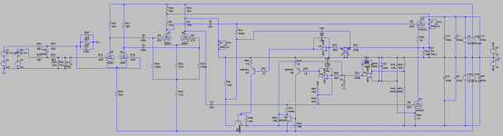
Yes, this schematics is readable (in my computer).
The only tube that has cathode far away from ground seems to be the bottom 6as7. Am
i guessing right ? Is the amp fed from + and - 200Volt ?
The bottom tube(U3) could in that case be supplied from AC filament where the DC level
is closer to -200Volt.
All other tubes seems to have cathodes close to ( within 50Volt) from ground.
How much AC feedback do you have in that circuit? Since you are using just one 6AS7 per channel, you would need some to bring the output impedance down to a useful level. Said feedback would also reduce noise at the output of the amp.
My supply rails are +/-65V, trying my best to keep the voltage low, since this is a headphone amp that is intended to be DC coupled to the output.
Cathode U5 and U6 is about 0V, Cathode U1 and U2 is at -40V while U3 and U4 are at output level and -65V. If its just a matter of keeping the heater voltage under the cathode voltage and staying within the limits of the tube, then it seems like i should tie the heater to -65V rail, or am i wrong?
Regarding feedback then i do have quite a bit. I got a range selection relay to adjust the feedback as this is both a preamp and headphone amp. The gain is -20dB from 0V to 200mVrms, and 0dB from 201mVrms to 2Vrms, with an output impedance of about 3-4 ohms.
- Home
- Amplifiers
- Tubes / Valves
- Switched DC heater vs AC