only problem with above input scheme is, tuner isnt working while playing
my main problem seems to be that I insist on the middle POS-2 to be the muting mode
I cant see how, and its very annoying
and btw, the muting mode would actually be the tuner in muting mode
in reality its just a second 'direct out' plug
should be easy, but.....
my main problem seems to be that I insist on the middle POS-2 to be the muting mode
I cant see how, and its very annoying
and btw, the muting mode would actually be the tuner in muting mode
in reality its just a second 'direct out' plug
should be easy, but.....
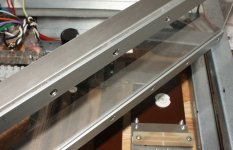
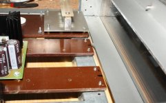
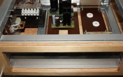
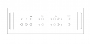
hey, while thinking about it, a few pictures😀
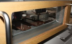
I managed to assemble the front
havent yet used the new smoked poly plate
so this is just some scatched clear poly, for the proto work
I managed to assemble the front
havent yet used the new smoked poly plate
so this is just some scatched clear poly, for the proto work
Attachments
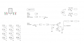
ok, regarding input switch toggle postions, I decided to change it
normal playing have to be the middle position
while playing you have both tuner positions available
tuning while playing, and silent tuning
funny how easy it suddenly becomes🙄
I call it audible tuning and silent tuning, because thats how I will use it
but preamp bypass would probably be more correct
Attachments
seems to be progressing well.
it feels better
less frustrated when I wake up in the morning 😀
looking at the effects loop
right before the tone control curcuit might be a good place
maybe the loop swithc could also do tone bypass🙂
but might be streching a bit too far
 but its tempting 😀
Attachments
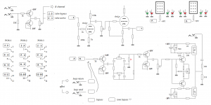
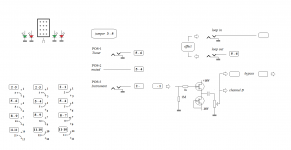
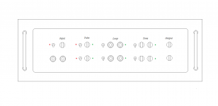
and possible front layout
getting crowded, but still doable, thanks to the LED's
if loop/bypass and tone bypass should be done with one and the same switch, then tone bypass will only work when effects loop is in bypass(off) mode
there is only 3 positions possible
but would be perfectly ok as there is no clean signal with effects anyway
hope that makes sense 😱
now I only have to put it together, and make it work 😀
Attachments
Hi Tinitus, don't worry too much on the switching as there are a lot of permutations. Just suggestion, but I would work on getting all the sections running with very basic switching for now, then you can see what works best and rewire the switches if needed.
.........work on getting all the sections running with very basic switching for now, then you can see what works best and rewire the switches if needed.
absolutely 😉
I know the effect loop will work
having tone bypass in the same switch probably wont
and I dont think I would throw in an exstra switch just for that
tone bypass is not that important
but a few filters could be....shoot, I forgot 😱
ok, I have put in a couple more switches for the tone curcuit, to prepare for any filters 😀 no more space for any further crazy ideas
I think design process is finished now 😛

Attachments

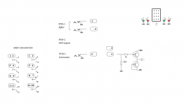
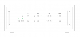
and here we go again 😱😀
revised layout(again)
one optional effect loop, just in case
the switch also do the muting
seem to work nicely with 4PDT with ON/OFF/ON function
and should still have plenty options to play with LEDs
revised layout(again)
one optional effect loop, just in case
the switch also do the muting
seem to work nicely with 4PDT with ON/OFF/ON function
and should still have plenty options to play with LEDs
Attachments
hmm, I have 3 option for splitting the signal
but which to use 😕
1. just take it from a mono pot, to each channel
2. use a stereo pot
3. use two buffers
but I will still use stereo pot for that one too
more practical with only one control at input
but which to use 😕
1. just take it from a mono pot, to each channel
2. use a stereo pot
3. use two buffers
but I will still use stereo pot for that one too
more practical with only one control at input
Attachments
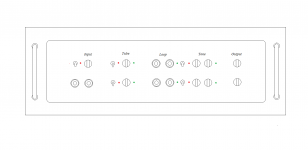
ok, I guess thats it
simpler now
LEDs
with the change to 3PDT switch with ON/OFF/ON, the mute comes natural
but I cant figure how to active a LED in that middle OFF position 😕
but then, if the green LED goes out, I guess thats good enough
and theres a nice bonus of using same ON/OFF/ON switch for the tube curcuit bypass
in OFF position it simply mutes each channel seperately
I think this will be a nice feature to have, for several reasons
and I looked at having a red LED for the OFF function, placed close to the output att-pot
same problem again
and could be solved by having a green LED activated in both tube curcuit switch positions, where there is a signal
if the greeen LED goes out, the channel is out, muted
who wants to look at a stupid red LED doing nothing anyway 😀
but should anyone know how to make the middle OFF position activate the red LED, I would still like to know, thanks
Attachments
Hi Guys
Have you ever tried any of the tube-equipped bass amps, like SWR? The gain stages are exactly as those found in Fender amps, using a single dual-triode like 12AX7.
With a guitar, two cascaded stages will only produce mild overdrive. A bass has more output, so two stages will produce a fatter distortion - but still more of an overdrive than saturated distortion. The Alembic preamp, the PV stuff, Earth, and any other name than including most old Ampegs use the Fender topology exactly, with only minor variations in the EQ values.
The best thing about the tried and true Fender arrangement is that it is built around the 12AX7. This is the high-gain member of a family of tubes that are pin compatible, so you can plug and play with less gain using 12AX7 (100), 12AT7 (70), 12AY7 (50) and 12AU7 (20). As you go down in gain (mu) the tone is mellower.
At the beginning of this thread, the high-z input question was not qualified as for a tube input or solid-state. All the correct answers appeared throughout the thread for both technologies. For solid-state, use a jfet. For tube, the standard input leak-resistor can be any value up to 33M with standard tubes. It is best not to use weird tubes if you wish to fulfill the stated desire for easy field servicing. As I showed in 'The Ultimate Tone vol.2' (TUT2), attaining high input impedance is easy with tubes.
The standard Fender second stage will drive a 100k amp input. It would be best if your PA had a level control right at the input. Otherwise, add a n output level control to the tube pre and then a buffer.
Have fun
Kevin O'Connor
Hi Guys
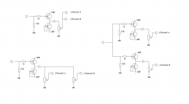
Using a center-off switch to control three LEDs is easy.
Wire the 'up' , 'down' and 'middle' LEDs with their cathodes to ground.
In series with the 'middle' LED wire two diodes. At the top of the diodes string add a resistor to the power supply. Connect the junction of the resistor and top diode to the wiper of the switch.
The 'up' contact of the switch goes to the anode of the 'up' LED.
The 'down' contact of the switch goes to the anode of the 'down' LED.
With the switch in the middle position, the middle LED is lit.
In the 'up' position', the 'up' LED is now inparallel with the 'middle' LED plus its diodes, which requires a higher turn-on voltage overall, so the 'up' LED is on and the 'middle' LED is off.
The same happens in the 'down' position with the 'down' LED.
This is called "current steering" and is explained in the Switching Methods chapter of TUT.
Have fun
Kevin O'Connor
This is called "current steering" and is explained in the Switching Methods chapter of TUT.
Have fun
Kevin O'Connor
thanks, will look at it
hey, I know its a bit confusing thread
its just one I have to let off my steam 😉
but sure, I am trying to build this thing 😀
Hi Guys
A steam-powered amp! It would probably sound like those carnival pipe organs.
Have fun
Kevin O'Connor
A steam-powered amp! It would probably sound like those carnival pipe organs.
Have fun
Kevin O'Connor
- Status
- Not open for further replies.
- Home
- Live Sound
- Instruments and Amps
- Switchable Hi-Z input impedance, how ?