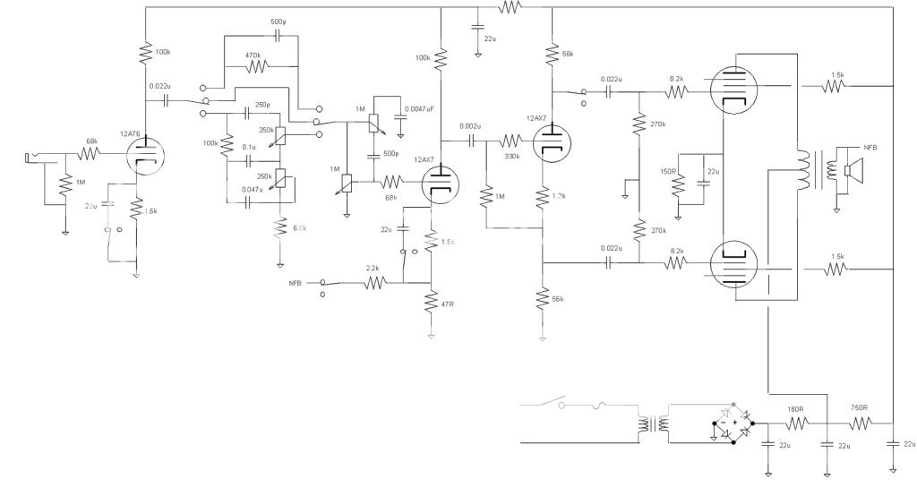
I drew up a schematic and wanted to run it buy everyone. I want to be able to go to a lower wattage with my amp with the flick of a switch. I want to have two different bias circuits and short the signal to one of the power tubes with a DPDT switch.
Will this work?
Will this work?
Attachments

If you add a 120R 2W resistor in series with the common cathode ground, that will reduce the output and keep the correct bias on the valves.
The 1R is to balance the bias of each valve independently. If you fit the resistor as I described, place your switch to short the 120R resistor out when you require full power.
The 1R is to balance the bias of each valve independently. If you fit the resistor as I described, place your switch to short the 120R resistor out when you require full power.
I don't want to go from fixed bias to cathode bias. I want to have two separate bias networks for each mode and just short the input signal to one of the power tubes. The reason for the two bias networks are because with just one 6V6 operating I want to raise the current flow further away from cut off.
I have done something similar in a small series heater string amp originally developed for the Hundred Buck Amp Challenge. I did not switch the bias, I just set it high enough for class A operation at low volume. I was using 50 cent 32ET5's which were designed for class A SE in line powered radios.
I had an issue, that you will also have with your present schematic. Your 22 uF shunting cap is too big and there is no provision to keep it charged. When you flip the switch the uncharged cap will instantly bring the associated grid to ground, and it will take several seconds for it to charge through the bias network. During this time that 6V6 will be very unhappy, and the current through the OPT will be grosssly unbalanced causing extreme distortion. There will also be a huge pop in the speaker when the switch is flipped.
You need a resistor from the ungrounded end of the cap to the point marked "B" in the bias circuit. The resistor needs to be just low enough to overcome the self discharge in the cap, say 1 meg or so. This will keep the cap charged to the same voltage that will be on the grid when operating in SE mode.
I found that a fair sized electrolytic (I think I had a 10 uF) still caused a pop , and a much smaller poly cap (.1 uf, maybe a .01) actually sounded better. It lets a little bass through the idle tube to fatten up the bottom, but also creates a midrange scoop due to the phase shift through the cap.
My amp design started out as a self split push pull design. It used the output tubes as their own PI. It only made 2 watts which is about what I could get out of a single tube in SE, so I kept modifying it until it worked. I now use a mosfet that is the split load PI in P-P mode and a source follower in SE mode. The amp makes about 1.5 watts in SE and sounds clean until pushed. It makes 6 watts in P-P and really screams. Both modes are cathode biased though.
I built this amp over 2 years ago, but never really liked it, so about a year ago I hacked up the PC board and sky wired parts all over it until I liked it. I have never gotten around to tracing it out to see what I did.
I built a small Class A amp that used a switch to turn off the signal to one of the output tubes. I did not short out the signal, just left the input to the tube float. I never had a problem with it picking up stray voltages but then again all my wires were pretty short. Think I put the switch on the other side of the capacitor though.
Thanks for the great replies.
I will try a resistor as mentioned from Tubelab to keep the cap charged. I don't get a pop through the speaker when using the switch but I might try a smaller cap like .1uf and see if I like it.
I will try a resistor as mentioned from Tubelab to keep the cap charged. I don't get a pop through the speaker when using the switch but I might try a smaller cap like .1uf and see if I like it.
I got it all wired up and it works really good. I can get my amp to break up much sooner with the low wattage mode and if I want classic Fender Blackface cleans I just hit the switch.
I am using a 22uf cap and don't get any pop. I also took Tubelab's advice and wired in a 1M resistor to keep the cap charged while in normal mode. I will play with it as is for now and then maybe try a smaller value cap like .1uf in the future.
I am using a 22uf cap and don't get any pop. I also took Tubelab's advice and wired in a 1M resistor to keep the cap charged while in normal mode. I will play with it as is for now and then maybe try a smaller value cap like .1uf in the future.
- Status
- Not open for further replies.
- Home
- Live Sound
- Instruments and Amps
- Switchable class