Hello,
I'm interested in integrating a switch that will allow me to switch an amp I'm working on between Pentode and Ultra linear operation. I am thinking of using a 3PDT switch configured as follows (for a single L/R channel of a push pull amplifier output stage):
Throw Position 1:
Pole 1 connects Screen Grid of 0 degree tube to Ultra linear tap of output transformer
Pole 2 connects Screen Grid of 180 degree tube to UL tap of output transformer
Pole 3 connects two current limiting resistors to ground. The other end of these resistors (in parallel to one another) is connected to two zener diodes in series, reverse biased to achieve the screen grid voltage I want in pentode mode. At this node, the connection between the current limiting resistor and the start of the two reverse biased zeners in series, is where the SG voltages are supplied in throw position 2.
Throw Position 2:
Pole 1 connects screen grid of 0 Degree tube to the lower voltage side of one current limiting resistor, with the two reverse biased zeners the sole path to ground.
Pole 2 connects screen grid of 180 Degree tube to the lower voltage side of one current limiting resistor, with the two reverse biased zeners the sole path to ground.
Pole 3 connects the ends of the current limiting resistors opposite the connection with the SG and the two RB zeners, to HT
To summarize, I'd have two parallel current limiting resistors feeding a node that connects to the pentode SG with two reverse biased zeners in series establishing a constant voltage. In throw 1 these two parallel screen grid paths are grounded on one end and open on the other. In throw 2, these two parallel paths are connected to HT by pole 3 and to separate SGs by poles 1 and 2. Now my question is that a typical 3PDT toggle switch datasheet shows a few voltage ratings at a few different currents; I've understood these basically to establish the amount of power the switch can handle. There is also a dielectric voltage rating, sometimes it's different between adjacent contacts and the switch body. My HT in this case is at most 350 VDC, more likely 310 VDC, and the total current through one switch pole is < 0.015 A. Therefore I'm far below the dielectric strength rating of a switch with a 1 kV dielectric strength. Extrapolating the allowable VA of the switch from the current and voltage ratings identified, the switch should be able to handle the power. I've included a link below to the switch I'm interested in.
https://www.mouser.com/datasheet/2/295/MtogglesBushing-334489.pdf
Am I misunderstanding the switch ratings? Is this application within the allowable range of operation for these switches?
If I were to only throw the switch with the power for the system turned off, is this a safe application?
If someone did throw the switch with the power on, what is the worst that would happen? I've heard that switching between UL and pentode with an energized system is bad for tubes / speakers.
Please draw up a schematic of your proposal, and post it.
A picture is worth 1,000 words.
Be careful. If there is a condition where one screen voltage drops to zero volts,
Then the plate may be able to go to 2 or more times the B+ voltage.
The only thing that might prevent this is that the tubes are in push pull (opposing currents). But that requires perfect switch make and break times.
But there is no guarantee that one switch contact will not open before the other switch contact; or that one switch contact will close before the other switch contact. That un-balances the current, and . . . Bang!
The nature of that type of transient voltage is that it is extremely quick. Faster than any switch contact.
The worst that could happen when switching while live could be damaging to tweeters, output tubes, output transformers, and your ears.
Perhaps you are wanting to do AB testing of Pentode versus UL mode on an instant basis, right?
Well, think about this . . . If your amplifier has Lots of negative feedback, the fact that all the parts are exactly the same, and the only change is Pentode versus UL, then remember the "Lots of negative feedback" will hide most or all of the sound differences.
The open loop gain of Pentode versus UL is different. But . . . The closed loop gain is the same if you have lots of negative feedback.
And most Pentode amps do have lots of negative feedback.
Just my opinion.
Last edited:
Some additional comments are:
The switch is rated for 250Vac, and has a test ac voltage withstand capability of a lot higher. You need to summarise worst-case working voltages across each and every switch contact on the same switch, and to the case of the switch.
The hassle is that output transformer winding voltages can far exceed B+ class A swing levels due to leakage inductance and non class A operation and other transient conditions like blocking distortion of the output stage. To some extent, those transient voltage levels can be constrained, such as by using MOVs, in a designed manner that keeps transient levels below the switch's 1 minute test levels - that could provide some assurance of acceptable performance of switch insulation.
It may be worth locating the switch on the chassis such that only you would toggle it, and to minimise connection wiring length and likelihood of high level signal coupling to where it isn't wanted. FWIW, I would do any live toggling, but if live toggling is deemed benign then only do it with gain/vol pots down.
Ok there should be an image attached. A rough, conservative prediction from the spice model I'm using suggests that 550 Volts peak for the plate and 420 Vp for the screen grid.
6A3sUMMER is right, basically all I want to be able to do is run the amp in UL mode for a while, turn it off and let it cool down for a few minutes, flip the switch and turn it on again in pentode mode. The chassis interior is getting a little crowded but I did consider putting the switches in the chassis so that no one could flip them when the amp was running. I'd still consider a mechanical element that prevents someone throwing the mode switches. Which is all to say that I don't have any intention of flipping the switch with the amp energized but if the switches are there, there exists the possibility that someone flips it when I'm not looking.
As far as feedback, what would you say is a lot of feedback? Could you estimate that in terms of output dBv reduction from open loop gain? I'm also evaluating some ways to provide adjustability to the feedback levels, but I haven't found any properties that really challenge component data sheet values for that portion of the system.
My number one concern is protecting myself and other people. After that, I just want to prevent damage to the amp itself. So maybe I should rephrase my question as, would it be safe to use these switches provided I could ensure that they were never thrown when the amp was energized?
It sounds like throwing the switches with the amp energized poses a meaningful risk of damaging the amp itself.
Attachments
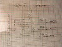
Ti83,
Thanks for the schematic, that makes it easy to see the switching issues.
A small folded aluminum box shaped cover over the toggle switch or slide switch should be enough to prevent someone from switching during powered operation.
Use star-head screws to hold the cover in place (screwdrivers need not apply here).
If the amp is always safe from un-attended children's hands that could get burned from hot output tubes, then it is safe from all except a practical joker who also reads this thread.
The issue of switch voltage arc over during opening of contacts goes away, because you only switch when the amp is unpowered and the electrolytics have been discharged by the B+ Bleeder Resistors. You do have bleeder resistors, right?
. . . Safety first.
In that case the only remaining issue of switch arc over is from switch section to switch section.
Ti83,
Estimate the open loop gain of your output stage this way, your output tubes will be different, and your output transformer primary impedance will be different, but here is the generalized concept. Just plug in your tube specs, and your output primary impedance to get the estimates:
(Do not worry about whether the amp is SE or Push Pull, the concept is to find the 'Ratio'
of open loop gain of Pentode, versus the open loop gain of Ultra Linear, not the absolute gain).
A theoretical output tube has the following characteristics:
Transconductance, Gm, 6000 uMhos (6mA/volt of control grid change).
Pentode plate resistance 18,000 Ohms, (large versus the transformer primary impedance).
Transformer primary impedance 6000 Ohms.
Triode connected u = 8 (u of control grid to screen grid; and the screen is connected to plate in triode mode).
Triode plate resistance, rp, 2000 Ohms.
Pentode gain is approximately Gm (6mA/volt) x 6000 Ohms primary impedance.
Gain ~ 36
Now we need to calculate the approximate triode mode gain, because Ultra Linear "u" is about 3 times that of triode mode u; and the Ultra Linear plate resistance, rp, is about 2 times that of triode mode rp.
(about = ~)
Triode gain is approximately u x (primary impedance/(primary impedance + rp)).
u 8 x (6000 Ohms)/(6000 Ohms + 2000 Ohms).
Gain ~ 6
So Ultra Linear "u" is 3 x 6 = ~ 18.
And Ultra Linear plate resistance is 2 x 2000 Ohms = ~ 4000 Ohms
The Ultra Linear gain is approximately 18 (6000/(6000 + 4000 Ohms)) = ~ 11
If the Pentode gain is 36 and the Ultra Linear gain is 11, the ratio is 36/11 = ~ 3.3
dB = 20 Log (base 10) of 3.3 = ~ 10 dB
Suppose your amp has 25 dB of negative feedback in Pentode mode.
Then having 10 dB less open loop gain in Ultra Linear versus Pentode, will leave 15 dB of negative feedback.
I expect the Pentode and Ultra Linear modes not to sound a lot different.
Pentode without negative feedback has an extremely low damping factor.
It needs lots of negative feedback.
Ultra Linear has a low damping factor. It usually needs some negative feedback.
Triode wired Beam Power and Pentodes have moderate damping factor, often do not need any negative feedback.
All Generalizations Have Exceptions.
Last edited:
The conservative opinions above are of course right.
However _I_ feel sure that a switch rated for large light or motor load at 250V will switch about any G2 voltage or current you are going to use in audio.
Even hot-switching. A lamp has huge inrush current. A motor has huge turn-off spike. In some commercial applications a switch must do its duty dozens of times a day and give useful life with benign failure mode.
Note that hot-switching G2 while music is playing loud is liable to POP in an ugly way. So you may, after you do it once, resolve to turn-it-down before hot-switching.
I am a bit confused by the zeners. In what circumstances would it be necessary to limit the screen voltage if a tube had already been operated in UL?
FWIW on the second amp I ever build, I used an ON-OFF-ON switch and relays to give me a 3 way triode, tetrode, UL switch. I attenuated the input for tetrode and UL so switching would result in equal gain in each topology. I switched it while the amp was running many times without any ill effects even with loud music playing. YMMV. The amp was a stereo PPP 6P3S amp running 460V B+ and using Hammond 1650N OPTs. The screens for tetrode were 75V below B+ by connecting the plate of a 0A3 tube to B+, the screens to it's cathode, and cathode connected to ground with a 100k resistance. One per channel (4 tubes).
I used cheap Chinese switches and relays for this, too. I don't recommend hot switching the output stage of your amplifier, but the switch/relay approach works well and relays switch faster than most switches, too.
I used cheap Chinese switches and relays for this, too. I don't recommend hot switching the output stage of your amplifier, but the switch/relay approach works well and relays switch faster than most switches, too.
Last edited:
Thanks for all the replies here.
The zeners are there to regulate the screen voltage in pentode mode— conceptually similar to using a VR tube. I’m considering putting a capacitor parallel to the zeners to stabilize that effect a bit, which I welcome opinions on.They are effectively out of the circuit in UL mode.
The relay is a good idea. I’m just a little loathe to use AC coil relays because it would require running another AC wire to the switch location. Conversely, a DC coil relay demands that I cook up another DC source for the coil supply.
I like the idea of mechanically enclosing the switches so that someone has to physically disassemble something to get at the switches.
I’m in no position to dispute 6AsUMMERS comments on the differences between UL and Pentode with sufficient feedback in place being nil. But as a hobbyist, I am interested in reaching that conclusion independently. You also spell out the feedback calculation very nicely. Ultimately, I think it will be fun to adjust the feedback settings in different tube modes, make some measurements, and hear the differences, which is what brought me here in the first place.
At this point I think my thought is to try the switches and just be very careful to ensure no live switch throws.
I find is better to regulate screen current rather than voltage as that is what does not go into the plate. A simple dropper resistor will work fine.
An AC powered relay will drop out when you power down the amplifier.
But there will still be B+ in the amplifier, so you will get a large transient in the amplifier and speakers.
A DC relay will require that there is enough capacitance to power the relay until the B+ voltage dies down, or again, you will get the transient in the amplifier and speakers.
And, the DC relay power also needs to come up rapidly, or if there is a quick power line drop-out and then the power comes back on, the resultant 'hot start' and the timing of it all may cause a transient in the amplifier and speakers.
Make it complicated, or make it simple.
Which is more fail-safe?
There are lots of examples of various ways to power the screen when the tube is operated in Pentode mode.
Some of the examples are:
A series resistor from B+ to the screen. You can find these from 100 Ohms to 10k Ohms used. The 10k 'attempts' to regulate screen current somewhat (not real current regulation). This is a form of local feedback, because the resultant drop of screen voltage consequently also reduces the screen current.
A resistor voltage dropper and VR tube(s), when 2 or more VR tubes are in series.
A resistor voltage dropper and Zener(s) in series.
A regulator chip, or a tube regulator circuit.
A separate screen voltage supply (a second B+, with no dropping resistors).
The discussion of advantages and tradeoffs of the above circuits could become another thread.
If you regulate Pentode screen current, you may get some very interesting results.
Whenever the plate voltage drops far below the screen voltage (as in many Pentode mode amplifiers), the screen will try to draw Lots more than the quiescent screen current.
That will result in the screen voltage dropping far below its quiescent screen voltage.
That means if you do this, the tube will "compress" the signal.
If you regulate the screen voltage, when the plate voltage drops far below the screen voltage, the screen current will be Lots more than the quiescent screen current.
But the screen voltage will remain constant, because of the regulated screen voltage circuit.
That means if you do this, the tube will Not "compress" the signal (compared to regulating the screen current).
Last edited:
Just set it up so when there is no power applied to the relays, it's connected as a triode. You get about the same noise as switching an input in my experience.
DC.
My pentode amp uses a VR regulator for the screens, and a minimal capacity on it's supply, so when power is turned off, the amp shuts up almost immediately rather than a long fade out as with triode connection. Still no loud pop or anything.
DC.
My pentode amp uses a VR regulator for the screens, and a minimal capacity on it's supply, so when power is turned off, the amp shuts up almost immediately rather than a long fade out as with triode connection. Still no loud pop or anything.
Regulating screen current for an output stage is complete non-sense. I was thinking of a long tailed pair driver (2 x 6EJ7) where the screens were connected to HT through resistors - but importantly a capacitor placed between them.
It may be possible to come up with a switching circuit (switch or relay) that is more silent by having some bleed resistor to the screen so that the voltage does not drop too much when the switch position is momentary o/c or you could use a make before break. In any case for a PP amp both sides will change within a few ms so the thump will be more of a click.
It may be possible to come up with a switching circuit (switch or relay) that is more silent by having some bleed resistor to the screen so that the voltage does not drop too much when the switch position is momentary o/c or you could use a make before break. In any case for a PP amp both sides will change within a few ms so the thump will be more of a click.
kodabmx,
Ti83 is switching between Pentode mode, and Ultra Linear mode.
He is not switching from or to Triode mode.
Ti83 is switching between Pentode mode, and Ultra Linear mode.
He is not switching from or to Triode mode.
Weighing in … on the side of “an ordinary hardware-store grade 3PDT switch will do just fine, combined with either a protective grille over the amplifier for protecting from kids, cats and idiot-friends”, is enough.
ONLY switch the switch when in power-down state, to be extra safe. Otherwise, tho', as KodaBMX and others have cited, although there will be a probably-loud audible click-thump when changing from A to B, both the valves and your speakers are quite well suited to take such thumps.
The neighbors, wife, sleeping kids and goldfish?
Not so much so.
⋅-⋅-⋅ Just saying, ⋅-⋅-⋅
⋅-=≡ GoatGuy ✓ ≡=-⋅
ONLY switch the switch when in power-down state, to be extra safe. Otherwise, tho', as KodaBMX and others have cited, although there will be a probably-loud audible click-thump when changing from A to B, both the valves and your speakers are quite well suited to take such thumps.
The neighbors, wife, sleeping kids and goldfish?
Not so much so.
KISS — Keep It Sturdy & Simple!
(I know full well that that is not what the acronym is… but it seems better, in this case)⋅-⋅-⋅ Just saying, ⋅-⋅-⋅
⋅-=≡ GoatGuy ✓ ≡=-⋅
- Home
- Amplifiers
- Tubes / Valves
- Switch Voltage Ratings