Hello all. I am trying to repair a 12V switching power supply which intermittently works and then stops working. Typically it may run for 20 minutes and will produce about 13V, then it will fail and the output will bounce back and forth from about 7v and up to 12v. It will pulse back and forth about once per second. This may last for seconds, or minutes, up to about 30 minutes, then it will go back to working again and hold a solid 13v. It does not appear to be related to temperature at all. I have changed all 5 electrolytic caps. I have a meter and an oscilloscope for testing. I am a hobbyist but have no experience with switching power supplies. Can anyone give me a hand with this? Thanks
Attachments
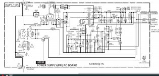
Here are some measured values on Q9001 MIP2M40MSSCF both in a working and non working state:
Pin ------ Working ----------------------Not working -------------------
1 VDD --> 5v ----------------------------- 5v
2 FB ----> 0v ----------------------------- pulsing between 0 and 0.2v
3 SO ---> 5v ----------------------------- 5v
4 VCC --> sawtoothish 9-10v ---------- pulsing between 5 and 15v
5 Drain -> 150v ------------------------- 150v
6 NC
7 Source > 0v GND ---------------------- 0v GND
8 LS -----> 0.2 V ------------------------ 5v
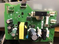
Also if it matters this is the standby power supply from an Onkyo nr818 amp. I bought it in this condition. I can tell I am not the first person to be checking this board.
Pin ------ Working ----------------------Not working -------------------
1 VDD --> 5v ----------------------------- 5v
2 FB ----> 0v ----------------------------- pulsing between 0 and 0.2v
3 SO ---> 5v ----------------------------- 5v
4 VCC --> sawtoothish 9-10v ---------- pulsing between 5 and 15v
5 Drain -> 150v ------------------------- 150v
6 NC
7 Source > 0v GND ---------------------- 0v GND
8 LS -----> 0.2 V ------------------------ 5v
Also if it matters this is the standby power supply from an Onkyo nr818 amp. I bought it in this condition. I can tell I am not the first person to be checking this board.
Last edited:
I'd look at pin 8 of the IC with the scope and a pamona grabber. That is feedback from what going on out there. Do same to pin 2 which is also feedback. Put a dvm on output at the same time, or use 2nd scope trace to show the dc value out. If a particular voltage correlate to bad voltage out, then you would have a clue. Hint, opto isolators die of too many hours service, too. Current transfer ratio can get a little low, not allow signal to get through. Transistors tend to die more permanently, gain doesn't usually deteriorate unless overstressed by excess voltage or heat.
Warning to newbies, 200 vdc from main AC is very dangerous. Use only one hand at a time, other in pocket when AC is on. Connect meters/scope to output ground with cliplead, not your hand. Wear safety glasses, this much energy can cause metal splatter. Wear no jewelry on fingers, hands, neck. Even 1 v through metal @ 50 amps can burn flesh to charcoal. Measure all metal at below 1v to output ground before touching it with bare hand. This may require discharging the main caps with a resistor soldered to a 600v rated test probe (old meter probe) and a ground clip. I use 470 ohm 10 W with solder tabs. Use 600 v wire for discharge device.
Warning to newbies, 200 vdc from main AC is very dangerous. Use only one hand at a time, other in pocket when AC is on. Connect meters/scope to output ground with cliplead, not your hand. Wear safety glasses, this much energy can cause metal splatter. Wear no jewelry on fingers, hands, neck. Even 1 v through metal @ 50 amps can burn flesh to charcoal. Measure all metal at below 1v to output ground before touching it with bare hand. This may require discharging the main caps with a resistor soldered to a 600v rated test probe (old meter probe) and a ground clip. I use 470 ohm 10 W with solder tabs. Use 600 v wire for discharge device.
Last edited:
I'd try shotgunning Q9004, the TL/KA431. If that goes wonky, you lose regulation. Before replacing it, look at the components around it.
Thanks for the replies! I did check the opto isolators out of circuit as good. I think I almost got it figured....
The plug in the upper right hand area sending the 12V out to the rest of the amp and with the 2 return lines is hard wired in so I could not easily remove it, but I figured I would cut some lines to make sure it wasn't something out there pulling the 12v down... With the ST power return line cut (which does eventually feed into pin 8), I got a solid 12V... I poked around some more and discovered my main relay on the coil side is intermittent (fed from the other return line). Could the system be setup such that if the relay was not activating to turn on the main transformer when being asked to that the feedback from SBPOWER causes this oscillation? With this relay removed from the circuit I get the oscillating 12V as usual. When I put in a new working relay I believe the 12V will be solid.
I am off the the store to grab a new relay. Will report back when new relay is installed.
Well new relay installed and it's been running for a day now which is longer than it ever has in the past, so I think its fixed!! I do not understand why it would not hold 12V with a dysfunctional relay.... I presume something to do with the voltage coming back on pin 6 from the rest of the amp?
It seems strange that the relay would be causing the problem. It might just be that the problem has gone away.
I'd replace all the caps.
I'd replace all the caps.
- Home
- Amplifiers
- Power Supplies
- Switch mode power supply repair