Just a quick update about my initial EL34B mods. I have a noticeable improvement in the mid range detail, tonal balance, treble clarity and extension by just doing the following:
* Removed and linked across the small red coupling capacitors on the input to the centre board.
* Removed the small electrolytic capacitors and 4 resistors on the front panel control board. Soldered links in place of the 2 outermost resistors and each capacitor. Note the resistors are 1k in series and 100k as shunts. There is absolutely no point i having these resistors just unwanted stuff in the signal path. This board is hard to remove as the control knobs appeared to be glued but eventually came off. Also the fixing screws are almost impossible to get to behind the large headphone resistors. Patience is called for here and a magnetic small screwdriver!
* Replaced the 4 x 0.1uF red coupling capacitors with 0.1uF K40Y-9 PIOs.
Much better..... but I still detect a kind of colouration to the sound perhaps caused by the valves in the pre-amp. I will be trying some Russians in there including a 6N1P in the driver. Following stuff on this thread I also see that it may be worth removing the cathode bypass, especially from the 1st valve stage to introduce some local feedback. I do have too much gain so this will help with that too.
Having said this, the sound is really so much better that it has leaped into being like something costing a few times more. I still can't believe the bass from this thing.
Cheers, Paul.
Yes, I removed the volume control knob without too much of a problem. The selector switch knob refused at first then the knob cover came off without the plastic insert / collar and finally this also slid off as it was easier to get hold of. I just need to re-glue the cover back in the right place. Note that the circuit diagram does not show these capacitors and shows the resistors as one set per input.
I just noticed that I found another unwanted electrolytic capacitor as previously noted by globulator, namely the one which is in the feedback loop. This needs to be replaced with a link and is completely unnecessary and not used in any other design I have ever seen. This is not in the circuit diagram.
Paul.
I removed the 220uF feedback capacitor and replaced with a link. This tightened up the bass a lot.
Then I changed the 100k V1 grid leaks to 1M to relieve the unnecessary impedance shunt. Having something here is worth while just in case the volume pot is ever removed or has a problem, although not really necessary.
Also I tried a 6N1P in the driver which was harsh at first but later then really cleaned up the sound right through the frequency range. It's early days yet but it appears to be more transparent and dynamic.
I am very happy with the sound now, next test is to try removing the cathode bypass capacitor for V1, a good idea as there is too much gain. However, I want to listen a bit more first as everything I listen too sounds so good.
I am collecting quite a lot of unwanted removed parts!
Paul.
Yes I never understood why they add so many useless components - they are supposed to be building to a price!.
That 220uF capacitor has no business being there in a speaker level output - it's just bizarre. These amps can sound absolutely fantastic with a little DIY input - it's quite amazing how much better they are than some eye wateringly expensive hi-fi you can buy.
Shame we cannot do a side-by-side comparison of our Peaches, I'd be fascinated to see how they compare with their very different topologies!
Bench Test results EL34B, original valves except driver is 6N6P:
I put the Peach through some simple tests and it performed well except for limited low frequency performance.
Measured output power at 1kHz (sine wave) was 5.8W
The high frequency response was good and started to roll off at 30kHz.
The low frequency response was good down to about 30Hz but at full power the output waveform became poor under 100Hz, with large amounts of distortion as I went lower.
However it remained undistorted down to 40Hz at no more than about 2W output power level.
These tests were done just by observing the output on the scope with a sine wave input.
A 1kHz square wave showed some ringing which I will look into.
I think the poor low frequency full power bandwidth must be the output transformer saturating.
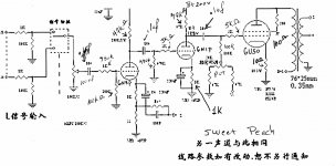
The above is what you would expect as the output transformer core size is only 76 x 25mm according to the circuit diagram. Also, there is only a small amount of negative feedback which would normally be used to extend the bandwidth.
I wish I had some better / larger transformers to try....
Paul.
I put the Peach through some simple tests and it performed well except for limited low frequency performance.
Measured output power at 1kHz (sine wave) was 5.8W
The high frequency response was good and started to roll off at 30kHz.
The low frequency response was good down to about 30Hz but at full power the output waveform became poor under 100Hz, with large amounts of distortion as I went lower.
However it remained undistorted down to 40Hz at no more than about 2W output power level.
These tests were done just by observing the output on the scope with a sine wave input.
A 1kHz square wave showed some ringing which I will look into.
I think the poor low frequency full power bandwidth must be the output transformer saturating.
The above is what you would expect as the output transformer core size is only 76 x 25mm according to the circuit diagram. Also, there is only a small amount of negative feedback which would normally be used to extend the bandwidth.
I wish I had some better / larger transformers to try....
Paul.
Good God man, you're only in Berkshire, we should meet up one day and compare Peaches!
Fascinating measurement set, esp about the 2W at 40Hz limit. Funnily enough negative feedback doesn't really help transformer bandwidth much because at the limits the gain is insufficient to _have_ any feedback, so the frequency extremes of a global feedback amp are effectively open loop anyway.
This is where my design and the Thorsten Loesch principle comes into it's own: Because GNFB doesn't help transformers (indeed it just adds a phase shift which invites instability) he tells us not to use it. So I don't. The performance of an output transformer is highly dependent upon the impedance that drives it, so I drive mine with a very low impedance drive, formed by having a very tight driver/power-tube feedback loop. This allows the OPT to get a much bigger bandwidth than the original Peach. (In theory - I have not measured it!).
Also bear in mind that the more bias running through the transformer the closer it is to saturation, it's a bit of a balancing act..
For the power 5.8W sounds about right. You can boost that by running in Pentode mode (which I do) but without the right circuit triode gives a lower impedance drive to the OPT and therefore will sound better.
Guys
It seems I have hit a rich vein of skill\experience here with you 2. I'll be removing the input caps and adding the bypass' to the bypass caps soon (free time is limited atm).
2 questions today:
1. I have noticed that one channel (right) has an occasional bit of distortion somewhere in the treble range (only above a certain volume but well before clipping). It is difficult to pin down, especially as it tends to be momentary but often appears with a female vocal - something akin to compression. I have tried tube rolling and speaker swapping as a first attempt at diagnostics but it is still there. Any ideas on where\what it could be?*
2. Have got hold of a scope and have a freq gen on my ipod - how can you run tests without having the speakers connected? 1000hz at close to clipping levels is not fun to listen to 🙂
Thanks
Dave
*I'm hoping that adding the bypass caps may sort it but have a feeling it is somewhere deeper in the pre-amp section.
To run tests with no speakers, you need an 8 ohm dummy load which will dissipate 5 to 10W, a wirewound resistor will do. If you feed in an increasing signal you may see the problem on the scope. It sounds like a dry joint, valve socket or one of the speaker switches (headphone or impedance sel). I had similar problems on my Leak ST20 and it turned out to be a dirty valve pin.
You could also try bypassing V1 and feed the signal into the 6N1 directly, after removing the nfb or just pull out V1.
Regarding the use of more feedback - it would help here since there is useful bandwidth but is is distorted under near full power. Yes, there are phase issues with transformers and nfb but there are many good amplifiers which do apply feedback across the transformers (which in itself is important because that's where some distortion occurs). This will certainly extend the power bandwidth, decrease the output impedance and reduce distortion. We would also create issues with feedback where we have RC networks in the path anyway. To have no or little feedback demands a very high quality transformer, which is what we really need for the pure SE sound. I am trying to get a couple made.
Given that we are using limited iron here in the transformers, then more nfb is a realistic option - I think we should try it. I am frustrated since we can't see the transformers to see what we have. I am also going to try no feedback and just one driver stage.
Paul.
WG: check the front selector switch (wiggle it a bit), and the tubes.
For casual testing just plug a headphone jack in, it then uses the resistors next to that!
I'd not recommend more feedback, the original circuits quite long (three complete stages and a transformer) so the chances are your phase margin will not be on your side.
I run my Peach without feedback around the transformer and it does exactly what Loesch said it would - amazing bass and fantastic treble - no bandwidth issues at all. Drive the transformer with a low impedance source and it rocks - rock music, heavy metal, blues, jazz, classical - all flawless and dynamic.
Read this: http://www.diyaudio.com/forums/tube...al-fb-decent-damping-factor-5.html#post525580
Also the amp is unconditionally stable now - which is nice, perfect square waves too.
For casual testing just plug a headphone jack in, it then uses the resistors next to that!
I'd not recommend more feedback, the original circuits quite long (three complete stages and a transformer) so the chances are your phase margin will not be on your side.
I run my Peach without feedback around the transformer and it does exactly what Loesch said it would - amazing bass and fantastic treble - no bandwidth issues at all. Drive the transformer with a low impedance source and it rocks - rock music, heavy metal, blues, jazz, classical - all flawless and dynamic.
Read this: http://www.diyaudio.com/forums/tube...al-fb-decent-damping-factor-5.html#post525580
4) If the output transformer is inside the feedback loop it limits the amount of NFB applicable severely and distorts much more (especially at low levels) than neccesary. Drive it from a low impedance and the problems are much reduced.
Also the amp is unconditionally stable now - which is nice, perfect square waves too.
You're right there is already quite a bit of feedback there in the original version but less than the classic amplifiers, such as the Leaks, which also have a lot more open loop gain. Thanks for the link, this is interesting.
If you get a chance, see how yours performs between 20Hz and 100Hz with a sine wave approaching full power. It seems OK at about half the full power input voltage, which is 1/4 of full power, where it then starts rolling off below 30Hz, which is pretty good. So there is no bandwidth issue apart from at the higher power levels. Your results will confirm if it's the transformer. I hope not! I would love to discover that we have some really good ones in there.
My Peach is fairly stable with a 1kHz square wave but shows a small amount of ringing, nothing too serious but the feedback capacitor seems a bit low so increasing this would help I think for the original circuit. Also the gain is quite high so removing the V1 bypass cap may also help with stability.
I also am getting excellent sound despite the above (saturation?) problem.
Paul.
Ok, typical. I had plans to make some more mods this weekend. The plan was to replace the coupling caps and add the bypass'. So, last night, off to Maplin I went. The electros were no problem but, from choices available to me for the 0.68u - they just had 2 off.
So my question today is, can I substitute a similar value (0.47u or 1u?) or is the value fairly critical? Bearing in mind, also, that they are likely to have only 2 of each, can I mix and match (but same each channel if that makes sense - e.g. 0.47u for the bypass and 0.68u for the feedback cap).
If not, it looks like I will be stuck for another week or so before I can do some more modding.
Thanks
Dave
Usually when I (used to) go to Maplins I'd select my part and they'd tell me it was out of stock. After enough times doing this I learnt and now rarely go there, if ever.
There is no 0.68u feedback capacitor as far as I know.. which one do you mean?
There is no 0.68u feedback capacitor as far as I know.. which one do you mean?
Attachments
Last edited:
Hi
I'm referring to your mods on the other Sweet Peach thread:
http://www.diyaudio.com/forums/tubes-valves/163459-trying-make-sense-sweet-peach-6.html
post 58, where you have replaced the 220u caps and added 0.68u bypass caps. This was what I was looking to do this weekend (as well as remove the input caps).
Dave
- Status
- Not open for further replies.
- Home
- Amplifiers
- Tubes / Valves
- Sweet Peach EL34b Amp - Distortion?