Zero Cool said:Any thoughts on swapping some IRFP9240/240 mosfets in place of some 5200/1943 bipolars???
hi,that need to check with your driver stage,maybe need more adjusting the value of device to fit with the MOSFET's Ugs(3~4V),but the BJT Ube just about 0.6~0.7V...
regards!
WINCO
Hi Zero,
you will need to calculate for the number of devices you plan to use what the slewrate will be.
Without any other changes except the output devices the drivers will need to feed the outputs capacitance with enough current.
Slewrate = driver current / total gate capacitance (Ciss)
Unless you alter the voltage for the output stage you will loose power because of the Mosfet threshold voltage.
IRF's have relatively high Ciss, 1300 pF.
To obtain a slewrate of 50 V/uS with four IRF devices the driver needs to deliver 260 mA.
The Toshiba's have a high current amplification, you will have to check if the drivers can deliver as much
Don't worry about any calculations 🙂 Unless you are modding a hyper fast amp you are wasting your time. It's even possible that the rest of the stages might not slew that fast anyway.
As the BJTs have relatively low current gain the driver stage should be up to the task. In practice it's a straight swap as long as you mod the Vbe mulitplier (bias generator) to generate the required increased bias voltage. If you are lucky the existing Vbe multiplier may have enough adjustment to achieve this without changing anything.
As mentioned the downside will be slightly less available max power output/voltage swing.
The best way to do it is to make Sziklai combination of BJT and MOSFETs with drains connected to load via small current sensing resistors. Average values of resistors are 33 Ohm in emitter of BJT driver with other end connected to drain of MOSFET, about 330 ohms in collector and collector connected to gate via 150 Ohm resistor to prevent oscillation. It is up to you to use any protection Zener diode connected between source and gate or parallel to 330 Ohms. Such a circuit enables you to get higher voltage swing at the output compared to source follower arrangement. Next you need only 2Vbe bias from Vbe multiplier. The best way to compensate temperature drift of output transistors is to put Vbe multiplier transistor at the same small heatsink of any BJT driver transistor.
Forgot to add on my post that you will need gate stopper resistors as close to the gate lead as possible. I achieved this by snipping the gate lead with about 4mm sticking out and soldering in a 0.125 watt resistor which then is connected to the board where the gate lead would normally be soldered. I used 470 ohms with IRFP240 and 510 ohms with IRFP9240 in my particular application. These values should suit most designs.
Allexx said:The best way to do it is to make Sziklai combination of BJT and MOSFETs with drains connected to load via small current sensing resistors. Average values of resistors are 33 Ohm in emitter of BJT driver with other end connected to drain of MOSFET, about 330 ohms in collector and collector connected to gate via 150 Ohm resistor to prevent oscillation. It is up to you to use any protection Zener diode connected between source and gate or parallel to 330 Ohms. Such a circuit enables you to get higher voltage swing at the output compared to source follower arrangement. Next you need only 2Vbe bias from Vbe multiplier. The best way to compensate temperature drift of output transistors is to put Vbe multiplier transistor at the same small heatsink of any BJT driver transistor.
All true, but we don't know if the design in question already has CFP output or EF output 🙂 It would take some major modding to implement a CFP output if it's an EF output.
Thanks for all the info. The driver stage uses A968 and C2238 TO-220 devices so they should have enough current available.
I am aware that I would need to add gate resistors. I usually use 220 ohms.
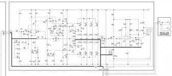
The schematic provided shows D2155/B1429 devices, but later models use C5200/A1943 devices. And even later models changed again.....
I have 2 of these modules and both have suffered a similar fate. I believe that are breaking into oscillation and blowing up. This is a Bass guitar amp so they get pushed pretty hard. the amp is rated for 350 Watts into 4 ohms and some players use a lot of slap and pop playing style and so this amp could see a lot of transients etc.
The output stage is very similar to the output stage of the Soundcraftsmen amps i work on so I am thinking a swap should be pretty easy. I’m looking to add stability and strength over audiophile type sound quality.
NOTE: Q311, Q312 are there for protection.
Also Not TH302, this Thermister mounts on the heat sink between the output devices.
The BIAS transistor is a C3200 and seems to be a pretty small device. I am thinking it’s not big enough to handle the Mosfets added requirements.
I would appreciate any suggestions for added stability. The only reason I want to switch to Mosfets is because they seem to be more robust.
R321 is a 150 ohm 2 watt resistor and always smokes when the amp blows. It runs VERY warm anyway. So this might need to be changed to a larger rating?? But my Soundcraftsmen’s use a 180 ohm resistor here and I don’t think it’s more that 2 watts so?
Zc
I am aware that I would need to add gate resistors. I usually use 220 ohms.
The schematic provided shows D2155/B1429 devices, but later models use C5200/A1943 devices. And even later models changed again.....
I have 2 of these modules and both have suffered a similar fate. I believe that are breaking into oscillation and blowing up. This is a Bass guitar amp so they get pushed pretty hard. the amp is rated for 350 Watts into 4 ohms and some players use a lot of slap and pop playing style and so this amp could see a lot of transients etc.
The output stage is very similar to the output stage of the Soundcraftsmen amps i work on so I am thinking a swap should be pretty easy. I’m looking to add stability and strength over audiophile type sound quality.
NOTE: Q311, Q312 are there for protection.
Also Not TH302, this Thermister mounts on the heat sink between the output devices.
The BIAS transistor is a C3200 and seems to be a pretty small device. I am thinking it’s not big enough to handle the Mosfets added requirements.
I would appreciate any suggestions for added stability. The only reason I want to switch to Mosfets is because they seem to be more robust.
R321 is a 150 ohm 2 watt resistor and always smokes when the amp blows. It runs VERY warm anyway. So this might need to be changed to a larger rating?? But my Soundcraftsmen’s use a 180 ohm resistor here and I don’t think it’s more that 2 watts so?
Zc
other options....
Hi,
I'm sure you might have considered it, but I was wondering why you might not go for slower and more rugged output transistiors. With some of the mje21193/4 or with more mechanical effort mj15003/4 type transistors, the SOA is increased, and the reduced Ft makes high freq instability less likely. You keep your current power envelope, and you don't have to cook the VBE multiplier to get 8 or 9v for bias...
Stuart
problems with r321
The power dropped in r321 is solely as a result of the level of bias voltage applied to the output stage...If the output were biased to a normal degree, perhaps 50ma each, this resistor should only have 1.2-1.3v across it, ie about 1/100w of dissipation, if it is hot at all I'd be measuring some voltages...something is not quite right...
Secondly, first glance would suggest the quadruplet of 2sc5200's is barely adequate for the task of 350w RMS into 4 ohms, assuming 70v rails, the toshiba doc shows at 25c the SOA for the transistor only allows a couple of amps, they don't give derating figures, but allowing 1w/c you are running really close to the ragged edge with those devices. If the manufacturer had used better/more transistors I don't think you'd have any problems. 4 x mje21193/4s will not have any difficulty here...
Stuart
Only because i have never had a mosfet fail on me!
I have beat the **** out of my mosfet PA amps on many nights and not one has failed. but ill be DANGED if the BJT amps havent died once or twice.... GRANTED, and lets not get into the discussion. these are different amps and different topologies and were talking apples and potatoes BUT..... I just thought Mosfets would be easier to implement and more rugged then a BJT type device... am i wrong to assume so??
Zc
Oh, And because my Killowatt partner just bought 4000, of the IRF parts for our Moster project so im sure i could purchase some of the rejects from our testing at a decent price!!!
Zc
Zc
The post's seem to be out of order....
Later models used the SC3281/SA1302 devices wich have a lower voltage rating.200 Vs 250, same 150 watts however...
I got my parts from ebay user active parts in NJ
Zc
Later models used the SC3281/SA1302 devices wich have a lower voltage rating.200 Vs 250, same 150 watts however...
I got my parts from ebay user active parts in NJ
Zc
Zero Cool said:I have beat the **** out of my mosfet PA amps on many nights and not one has failed.
That is one thing i agree with, ZC.
(i am gone keep that, ZC sounds hot)
I think many musicians would rank their fav output devices as:
1 Tubes
2 Mosfets
3 BJT's
For the sound but also for reliability.
My guitar fool neighbour just asked me recently to build him a tube amp.
(i am brainwashing him into Mosfet solid state with a double tube front.)
In my scavenger years i wrenched a load of Hitachi SJ/SK's out of abandoned amplifiers, not 1 device was out of order.
(and many were used or built for pa work)
A couple i built an output stage with, hooked up a dummy load and a generator, and drove them into 1st thermal breakdown.
Each and every time the Mosfets recovered after a cooldown.
That the company switched to Toshiba's 2SA1302 and 2SC3281 later must have had a reason, SOA of those devices is a lot better i think.
Stuart made a good point.
I had a Stage Accompany SA1600, a design with Matti Otala's signature.
(Yep, a very fast one, used BF469/470 video transistors)
With 10 Sanken's in MT200 outfit per channel it delivered 500 plus in 4 Ohms on 96 volt rails.
Great amplifier, but drive it hard and it would go into protection mode.
It was tested once, driven at 250watts in 4 Ohms the heatsinks reached +200F within 5 to 10 minutes.
Like Stuart said, TO3's would be a better choice than TO247's i think.
In his words i missed the comparison of SOA of IRF's to the Toshiba's.
If the amp is used for PA work and equipped with a vent, could a higher volume vent not be an option to make the amp job reliable with IRF's mounted ?
btw : if your Beamer ever needs new glazing, just park it in front of your future amplifiers.

Better still, put the missiles on the back seat and you'll have an 850 V12 coupe convertible !!!
(still, best looking BMW ever built, except for the M1)
mosfets are better...
...for reliability, freedom from secondary breakdown and a nice good temperature coefficient makes a massive difference, but...
Problem is the dimished output voltage, and much increased output dissipation...
The IRF's will actually dissipate a lot more heat at any given power output, the 4-5v extra makes a huge difference in an AB amp, the peak power point is shifted, and the 'almost clipping' dissipation is much higher, you'd really want to make sure the thermal protection is working if you are shooting for peak power output...
For a single datapoint: when the amp is putting 700w peaks into 4 ohms, the BJTs were seeing somewhere between 0.5 and 10v at 13 amps (no idea about specific rail sag), so their (per transistor bank) instantaneous power is 5-130w. At similar output levels, assuming the power supply has the additional headroom, the mosfets are gonna see from 5-15v, the dissipation is more than doubled to 65-195w...
Electronically such substitutions are definitely possible, but most amps are designed down to a budget, and heatsinking is one area where they are not going to give you 'too much', my experience suggests 'barely adequate' would be a better description.
I'm not one to discourage experimentation, but I'd suggest BJTs are the way to go here...just use the right ones and the amp will live happily ever after...
Stuart
Surely the power dissipated in MOSFETs under saturation is exactly the same as with BJTs? The rails are the same and the voltage at the speaker is the same and the current will be the same. It therefore follows that whatever device is in there must be dropping the same amount of power.
It's only when you run out of drive due to the increased gate voltage requirement and higher saturated on resistance that the difference will be apparant.
It's only when you run out of drive due to the increased gate voltage requirement and higher saturated on resistance that the difference will be apparant.
not quite...
The saturation voltage for mosfets of the IRF240 calibre is probably lower, but unless you drive them with additional voltage you are not going to get them to saturate. You are always faced with the ~5v needed to make them conduct. Changing the amp to allow for higher voltage drive is not hard, but adds considerable complexity to the swapping rework...
At the point where the system runs out of volts for drive, and is therefore clipping, there must be ~5v across GS of the mosfet, or it isn't conducting, since in this case D & G are held to the same voltage, there's ~5v across the device...there's a very good reason why every well designed mosfet amp uses a higher rail for the VAS etc, it actually reduces the size of the power supply needed to achieve a given output power...
Now my reasoning may be flawed, and I'm happy to hear where and why, but as far as I can see this is not the correct rework for this particular scenario, I still maintain a quad of mje21193/4 will be the best answer...
Stuart
- Status
- Not open for further replies.
- Home
- Amplifiers
- Solid State
- Swapping IRFP9240/240's for SC5200/SA1943's??