Hi Guys,
I hope I ask this question so I can understand the answers!!
I recently got 2 console amps, ( pics in other threads), a Motorola 3channel amp, which is just an amp pull, no preamp, tuner, speakers, etc,,,
The other is a Magnavox record player only console, this one has two separate speaker cabinets, One has the amp, a preamp of sorts, (just pots, caps and resistors, connected to RCA male- female jacks,that connect from the phono, thru the preamp, and into a 7025 tube in the amp chassis... The other is just speakers and record storage...
Here's the question,,, I was thinking of making the 2 channel Maggy a stand alone amp, and putting the Motorola amp in the Maggy cabinet,,, How can I convert the Maggy controls to the Motorola amp? I figured I could hook mids and tweeters to the Motorola L-R channels/speakers and the 15" low range speakers to the third, bass channel, with a separate VC for the bass channel....
Thanks for tolerating these novice questions!!
Regards,
John
1st things 1st! Post a schematic of the Motorola amp. I've seen "3 channel" setips that used only 2 power O/P tubes. They used the power tubes single ended for the upper registers and, simultaneously, push/pull for the bass. Another example of a "Bean Counter Special". 🙁
Sacrificing the customer on the Altar of Profits is a time honored big business practice. 😡
Sacrificing the customer on the Altar of Profits is a time honored big business practice. 😡
1st things 1st! Post a schematic of the Motorola amp. I've seen "3 channel" setips that used only 2 power O/P tubes. They used the power tubes single ended for the upper registers and, simultaneously, push/pull for the bass. Another example of a "Bean Counter Special". 🙁
Sacrificing the customer on the Altar of Profits is a time honored big business practice. 😡
Hi Eli,,, Thanks for replying,,, I needed a project while waiting for the Philco parts!!!!!!
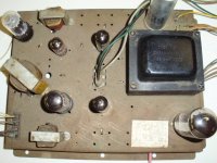
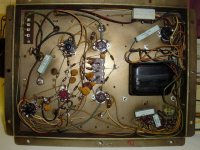
Here's a couple pics,,, I believe this amp is as you described,,,the schematic is not exactly like my amp, but its pretty close...
Regards,
John
Attachments
This time around, you have a power trafo. 😀 That power trafo has some "stones". Hurah!!
What rectifier does your specimen use? I suspect it's either a 5U4 or a 5V4. The sticker next to the rectifier seems to be a schematic. If it is, use your camera to shoot a pic.
The schematic PDF you linked shows (YUCK) signal processing circuitry. Early home theater, anybody? 🙁 "Vibrasonic", indeed. :roll:
A 6V6 has lost envelope integrity. Bury that "soldier" with full honors.
IMO, the real value in this Motorola carcass lies in the PSU and sheet metal. I don't think sufficient "real estate" is available for the mounting of Z565 O/P trafos, but 2X Edcor GXPP15-8-8K should fit. To get "full" bass extension, the limited power O/P of triode wired "finals" is in order. Otherwise, I envisage something employing PP 6CM6 (which is more or less a Noval based 6V6) "finals" along the lines Jeff Yourison is following here, with 6Y6s. The B+ rail voltage issues discussed are not present here. 😉
one at a time...
This amp is THS1078A, the " T" indicating the console includes a TV set, as far as I could find researching...
The trans does have "stones" too many, is the problem... it came from a console with tuner/preamp/reverb, at least, powered from teh PT, so the voltages are high, without the original load...
I checked all the pin voltages, and found the plates for the 6BQ5's, run about 36v higher than the schematic I have,, it shows (306V),, with a maximum of 300v in the RCA manual...
The 6V6GT's run 327 & 334v, the schematic calls for 300V, but the max on them is 350V... I realize I don't have the exact schematic for this amp,,,, but I'm sure the voltages have to be lowered, at least with in the tube specs, correct? How can I do that? I have the PS caps ordered, but, I don't think they will lower the B+...
It uses a 5U4 rectifier,,, two 6BQ5 SE, for L-R,, and 2 6V6 PP for the bass channel, and a 12AX7... I replaced one 6V6 with a spare I had on hand, as one was physically damaged,,,
Before I modify this guy, I would like to see if I can get it working, more for experience than anything else,,,, Am I correct assuming I will need a preamp to push the volume to a usable level?
I can't get usable pics of the tube layout.
Regards,
John
You are overlooking the voltage drop in the cathode bias networks. However, the were not gentle with tubes, back in the day.
Odds are a CDP can push the SE stereo channels into clipping. All that's needed there is a passive volume control. 😉
Odds are a CDP can push the SE stereo channels into clipping. All that's needed there is a passive volume control. 😉
You are overlooking the voltage drop in the cathode bias networks. However, the were not gentle with tubes, back in the day.
Sorry, Eli,, I don't understand your comment...
Odds are a CDP can push the SE stereo channels into clipping. All that's needed there is a passive volume control. 😉
Can I build a "passive VC" into my chassis? If so, can you recommend a simple schematic?
From what I read, it would work best with the shortest leads,,, Seems, its just a high quality pot, and maybe, resistors....
I appreciate your help,
Regards,
John
Can I build a "passive VC" into my chassis? If so, can you recommend a simple schematic?
From what I read, it would work best with the shortest leads,,, Seems, its just a high quality pot, and maybe, resistors....
I appreciate your help,
Regards,
John[/QUOTE
Isn't this a passive preamp?? It plugs into the Maggy chassis,,,,
Attachments

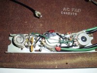
Isn't this a passive preamp?
Sure looks like it. HOWEVER, I see nasty ceramic caps. and other music killing stuff. You can try that "kludge", but ... I strongly suggest you simply buy a pair of inexpensive 10 KOhm log. taper pots. from either Mouser or "Rat Shack". Use those parts to control the volume/balance of the signal originating at a CDP. Add additional resistance in the "hot" lines leading to the controls, if a "hair trigger" condition rears its ugly head.
Sure looks like it. HOWEVER, I see nasty ceramic caps. and other music killing stuff. You can try that "kludge", but ... I strongly suggest you simply buy a pair of inexpensive 10 KOhm log. taper pots. from either Mouser or "Rat Shack". Use those parts to control the volume/balance of the signal originating at a CDP. Add additional resistance in the "hot" lines leading to the controls, if a "hair trigger" condition rears its ugly head.
I think I have a set of 5K pots.... I have to recap this amp, and I'll try those on the inputs,,, no sense recapping the preamp, if it won't work with the Motorola,,, but, I'm hoping I can use the Maggy controls to control the Motorola,,, then, the console will look original, from the outside, anyway!!!
Regards,
John
Put 5.1 KOhm resistors in series with the controls from your "pile". A commercial CDP should be fine working into that load, as 10 KOhms is IHF "standard". OTOH, going below "standard" is asking for trouble.
Put 5.1 KOhm resistors in series with the controls from your "pile". A commercial CDP should be fine working into that load, as 10 KOhms is IHF "standard". OTOH, going below "standard" is asking for trouble.
I have a new pair of Mouser 5K pots, and I can put them in series with a pair of 5.1 K ohm resistors....Should I bypass the amps input jacks, et al,, and just wire my pot/resistor to the 12AX7 grids?? How about using a tape deck, for testing, as that's what i've been using?
Thank for your continued help...
Regards,
John
Linear taper pots. will not do and that's what I suspect you have. Mouser stock # 313-2440F-10K (Alpha 10 KOhm log. taper) costs $1.55 and "Rat Shack" will not be grotesquely higher.
What kind of tape deck have you been using? If it is a mainstream consumer audio unit, it should be capable of driving the 10 KOhm IHF "standard".
OK ,, I'll check the pots,,, pretty sure there is a mouser part number on them.. I'll get teh right ones, if they are linear.... the TD is an old panasonic cassette deck,, it seems to work fine on any amp aux or tape input...even teh old ceramic cartridge phono amps I've been working on...
Thanks for your help...
Regards,
John
Last edited:
I found the pots, and resistors, and wired them between the TD outputs and the L-R amp inputs, and it doesn't change volume at all, The passive VC passes the signal as if it wasn't in the ckt...
Is there an "open circuit" left on this Motorola chassis, since the tuner and tuner wiring has been eliminated, like the 390 Ohm resistors needed on the Maggys ??
Regards,
John
Is there an "open circuit" left on this Motorola chassis, since the tuner and tuner wiring has been eliminated, like the 390 Ohm resistors needed on the Maggys ??
Regards,
John
- Status
- Not open for further replies.
- Home
- Amplifiers
- Tubes / Valves
- swapping console amps...