Hello, I have a question about amp testing that I hope someone can give me some insight on. I am not sure if this is the right section to post this question. I have replaced the entire power amp section of a SVT 6pro amp and have been trying to verify that it wont blow up in a live setting. This is a 2ch bridged amp with 5 sets of mosfets per channel driven by 12au7 tubes.
While load testing 1khz into 4 ohms, somewhere around the 400w mark, after around 20 sec or so, the output shrinks slowly and the signal looks distorted (jagged flat top, crossover region not smooth). I can repeat this testing behavior, so the lowering of output appears to not be permanent. What bugs me here is that the first time I noticed this behavior, I had it at 600w 4 ohms for a whole minute before it did this, raising fears that I nuked something.😕 It still works, but I cant repeat that 600w test for as long as originally.
I am not certain if there is a protection mechanism that can slowly (over 10 sec) cause the output to shrink and distort. As far as I know, it only has VI limiting to restrict drive to the gates and a overtemp/voltage relay shutdown, but I thought that would be more abrupt.
I can quickly (for a couple of seconds) bring it up to 1000W and clipping without anything weird happening, so I am assuming the output mosfets are still ok... Is it possible that the tube drive or input stage is doing this instead of the power amp limiter? If someone could point me in the right direction, I'd appreciate it.
Info about the amp? Or do we hunt?
It should go 1,100 Watts in 4 Ohms for many-many minutes, even hours. It should clip for days (or until the dummy-load sets your shop on fire). If it won't, then don't put it on stage.
A "feature" is a power voltage control. It has a knob. It may also have "smarts", allowing gross excess but only for a short time.
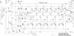
Thanks for the reply, here is a schematic of one half.
The power amp section seems simple enough, which is why I am a little confused as to how a gradual power reduction could possibly take place. All voltages check out according to the schematic. The power supply is pretty standard too.
I am not exactly sure on all aspects of operation, but I see the 13v zeners voltage limit to the gates. Q5,Q6 for limiting drive voltage based on current through source resistors, but wouldn't this be more or less instantaneous and not gradual? I am guessing that Q3 and Q4 are a bias balancer of sorts with IC2 a feedback to control it? My initial thought is that it is heat related, but the thermal stuff works, fans and shutdown seem ok. Could it be Q5 and Q6 throttling the drive somehow?
I replaced all mosfets, source R's, gate R's, and the 2.2k sense R's, 2 of the 13v zeners and Q6 when I repaired the output boards.
The input stage has all kinds of stuff, but none of it seems likely to affect the output mid load test.
Attachments
Ok, the 12au7s couldn't handle driving the OPS and were acting up. Seemed to be interacting with the tube voltage adjustment. Works now with my older Sylvania test tubes...
- Status
- Not open for further replies.