My old Technics amplifier went dead. I suspected the power IC SVI3205 may blown.
How can I determine?
I read from a book that checking on-board IC can be done by measure the resistance of the chip's individual connector against the ground (positive & reverse). Take the reading and then verify against the resistance value provided by the manufacturer to determine the IC is bad or not.
Is that work?
However, I can only found the chip diagram from the following website but no resistance value found:
http://www.geocities.com/technicshifi/SVI3206.jpg
Could someone kindly provide me the resistance value I want?
Also, I can't find this SVI3205 IC in digikey.ca. Is any model of STK or LM series IC could replace it? I think it's easy to find and must more cheaper.
Thanks in advance for your kind assistance.
i dont
belive that procedure like that exists
but in any case you can do the most simple like take a first look that where the out of your chip is per channel you should get 0 volts ...... if in the pin of the out you have any more than 50mv your chip is doomed
when chips are gone ,their output transistors are shoretd resulting DC voltage in the output fo course you dont see any of that since protection relay is activated to protect your speakers
on the other hand normal tests like rail voltage fuses gone and other normal stuff is presumed allready done ...or mayby not ?????
let us know
Dear Sakis,
Thanks very much for your information.
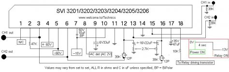
I had performed voltage test on the IC pins. From the diagram found on the net, the output pin should be pin 3 and pin 6.
On pin 3, I got 0V but in pin 6, it was 51.3V.
Also, the diagram shown pin 18 should have 0 to 13V within 4 sec. The test result is only keep -0.1V even held longer than 4sec.
I think the chip was already GONE.
Now I have to look for the replacement, but it is hardly to find on the net.
Thanks again for your help.
Thanks very much for your information.
I had performed voltage test on the IC pins. From the diagram found on the net, the output pin should be pin 3 and pin 6.
On pin 3, I got 0V but in pin 6, it was 51.3V.
Also, the diagram shown pin 18 should have 0 to 13V within 4 sec. The test result is only keep -0.1V even held longer than 4sec.
I think the chip was already GONE.
Now I have to look for the replacement, but it is hardly to find on the net.
Thanks again for your help.
i have the same issue
pin 3 0v
pin 6 52v
pin 18 0.1v
did you change the svi3205 and is it now ok ?
pin 3 0v
pin 6 52v
pin 18 0.1v
did you change the svi3205 and is it now ok ?
Unfortunately, those SVI chips are no longer made, and a micro-slim chance of ever finding a "real" replacement.
Those technics units using them, if still good, must be thoroughly gone over to prevent SVI failures from happening.
Their soldered pins need re-doing to insure positive contact on the board, along with the heatsinked regulators next to them.
Associated capacitors need checking/replacing.
The fan cooling system (if used in some models) must be modified to provide continuous operation by re-working the fan triggering transistors along with an addition of a thermistor mounted on the heatsink to ramp up fan speed as the heatsink gets warmer (they run hot normally).
This of course requires a knowledge of how to design such a system.
A quiet-running computer-style fan was my choice as a replacement over that noisy stock fan.
Keeping that SVI comfortably cooler makes it last.
I did this to my Technics receiver years ago, and it's still going strong, and gives me peace of mind.
Last edited:
I have a Technics eBay amp SU-X501 with the SVI3204 chip.
No sound.
Protection relay operation okay
Audio input signal on pin 13 and 15 (checked with scope)
Only a few millivolts on the output pins 3 and 6
Most voltages are correct but only -0.027v on pin2 and pin9 -4v
I can't find and information on what those pins do and was wondering if the module is in mute rather than failed.
Is failure like this also normal?
Anyone got a diagram with Information on what all connections to this are for?
I see BC branded replacements exist (BC brand on some factory chips in Technics amps) but as suggested they may not be anything like the originals.
Many thanks but alas like many of the drawings it does not say what all the pins do.
Pin 2 and Pin 9 seem to be a mystery 🙂
Pin 2 and Pin 9 seem to be a mystery 🙂
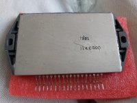
Back in February I ordered a SVI3204 which finally arrived (actually a SVI3204B).
Fitted it an powered on and much as I expected it did not work and actually smoked from the top right side.
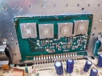
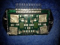
When removing the old module the cover fell off which revealed the internals and it looks like similar pictures of the device.
Got the cover of my new SVI3204D and it is very different inside.
3 X small IC's 6 X big devices, two square and four rectangular shape and five of them with four wire connections on front.
On removal I also noted the back heat sink surface was not flat as no compound I put on the device was left on the amplifier heat sink.
Should a SVI3204B have worked? Is it just best to skip any amplifier that needs a new one of these modules?
Fitted it an powered on and much as I expected it did not work and actually smoked from the top right side.
When removing the old module the cover fell off which revealed the internals and it looks like similar pictures of the device.
Got the cover of my new SVI3204D and it is very different inside.
3 X small IC's 6 X big devices, two square and four rectangular shape and five of them with four wire connections on front.
On removal I also noted the back heat sink surface was not flat as no compound I put on the device was left on the amplifier heat sink.
Should a SVI3204B have worked? Is it just best to skip any amplifier that needs a new one of these modules?
Attachments
Last edited:
Seems likely that IM35461 got a fake IC replacement.
Because technics/matsushita has stopped manufacturing them years ago.
Also, the regulators mounted on the heatsink and their associated parts should be thoroughly checked, regulator outputs re-soldered, etc., because the SVI chip relies on those for proper operation.
If that was not done, and there was faults with them, then no SVI is going to work properly.
The surrounding transistors were checked and are still okay (it would seem).
Removed, tested, new heatsink compound and put back.
The connections of my fake / different module don't seem to match up with pins 3 and 6 not going to the output transistors. They do on the old one.
I now think rather than the smoke coming from the module that perhaps a resistor on the amp PCB was being overloaded.
All the low resistance ones in the area seem okay and power was only on briefly so perhaps survived the overload.
I have a SVI3206D also on order and I may try and source another amp with the same chip and try swapping it putting a known good one in to see what happens.
IM35461
The 2SA on Lch had burnt out, and likely has gone open.
Unbelievably some putrid turd had de pinned a Class H+ RSN module And popped a 3204 cover on it.....
The 2SA on Lch had burnt out, and likely has gone open.
Unbelievably some putrid turd had de pinned a Class H+ RSN module And popped a 3204 cover on it.....
IM35461
The 2SA on Lch had burnt out, and likely has gone open.
Unbelievably some putrid turd had de pinned a Class H+ RSN module And popped a 3204 cover on it.....
You're good.
How can you tell?
I've never opened up one of those SVI chips, when they went bad, I'd simply replace them. (with original Technics stock)
I remember way back then, they cost $30-60, but that was charged to the customer of cource.
Matter of fact, my own receiver uses a SVI3205 chip (60/60w), but with fan mods, replaced caps, I'm not worried.
Indeed, found a YouTube video showing the provided fake chips real identity.
No wonder my amp did not like it.
RSN309w44 inside hybrid ic matsushita - YouTube
No wonder my amp did not like it.
RSN309w44 inside hybrid ic matsushita - YouTube
You're good.
How can you tell?
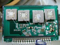
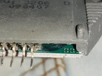
Look closely at the silicon dies on the blocks... on the 2nd one you can see the blackened area right where emitter wire connects
Usually with SVIs it’s Blockslide that causes havoc
See pics - this happens if cooling fails
Attachments
Last edited:
Look closely at the silicon dies on the blocks... on the 2nd one you can see the blackened area right where emitter wire connects
Usually with SVIs it’s Blockslide that causes havoc
See pics - this happens if cooling fails
Thanks for that info.
That is why, years ago, I modified my Technics receiver's cooling system.
Because those SVI's are well known to run on the hot side.
While I like Technics a lot, sometimes I have an issue with their way of ventilation in some products.
You probably know that the fan is driven intermittently by speaker levels triggering a set of transistors, kicking on the fan.
And that fan is a crappy design as well, it gets noisy.
My modification uses a thermistor mounted on the heatsink, controlling the transistors in a gradual "ramp up" way as the heatsink warms up.
And the fan is replaced with a suitable computer type fan which is quieter, along with some aluminum shrouding from the fan to around the heatsink to focus more airflow though its fins.
The system works quite well! 🙂
You’re right with the fan setup
Often bearings dry up in the motor, making it draw more current... taking out the driving transistors....
The other setup (heatpipe) runs into trouble if not level - moreso if liquid is not getting behind SVI - (often if power Xfmr side sitting higher than other side)
Often bearings dry up in the motor, making it draw more current... taking out the driving transistors....
The other setup (heatpipe) runs into trouble if not level - moreso if liquid is not getting behind SVI - (often if power Xfmr side sitting higher than other side)
You’re right with the fan setup
Often bearings dry up in the motor, making it draw more current... taking out the driving transistors....
The other setup (heatpipe) runs into trouble if not level - moreso if liquid is not getting behind SVI - (often if power Xfmr side sitting higher than other side)
Yes, and I changed the fan driver transistor to a higher current one, rated for 3 or 4 amps in a TO126 package.
Added in a tiny potentiometer to set the initial power up speed low when cold...... thermistor ramps it up slowly as it warms up, but still runs quiet.
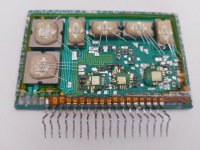
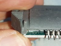
No response from the seller on aliexpress re my fake module which I gave a 1 star rating.
Anyway, today my SVI3206 D from an eBay seller and this one looks different and hopefully real.
Any thoughts?
Anyway, today my SVI3206 D from an eBay seller and this one looks different and hopefully real.
Any thoughts?
Attachments
Last edited:
- Home
- Amplifiers
- Chip Amps
- SVI3205 measure and replacement