Linear PSU +-64V with no load connected.
With amp connected it flies up to +-70V causing the OVP to kick in (I assume).
When I shut it down the blue LEDs comes on briefly indicating oscillation.
Putting resistors across caps should theoretically work but may not be the most elegant solution.
This is for a sub so only one channel is used. I connected a resistor across the unused channel but the problem did not change.
Turning it off and then on again when oscillation is indicated makes it work for a while.
It seems it trips OVP at times causing oscillation to stop.
+rail measures around 67V when running
Any ideas?
It seems it trips OVP at times causing oscillation to stop.
+rail measures around 67V when running
Any ideas?
Am I right in assuming that the Sure board is based of IRs own reference design AMP7D-200?
That would mean that the OVP diode should be a 91V zener and not 68V.
How likely would it be for the rail to be pumped up to 91V from 68V thus needing the protection in the first place?
Meaning the workaround would be removing the zener altogether.
And I still don't understand why hooking the amp up results in higher rail voltage compared to unloaded.
Measuring the rails unconnected again does show +-70V. Annoying as I measured it just before connecting to be sure polarity was correct and it showed 65V. Gah.
+-70V is still within tolerance though so the board should have been fine with it.
Is the Z100 on the Sure board the same and controls the OVP?
+-70V is still within tolerance though so the board should have been fine with it.
Is the Z100 on the Sure board the same and controls the OVP?
In a completely related event the zener is now somewhere on the floor and the amp works just fine.
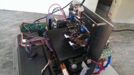
Not sure what there is to post. PSU is a simple center tapped transformer with one bridge rectifier and two caps, rest of hookup is straight forward.
Found out that one of the channels didn't like 10k resistors for the house keeping supply, they where slightly bigger than the included in size but still got smoking hot (literally).
And I didn't find any bigger resistors laying around, Ill have another look but it might be better to attach the resistors to a metal plate that the amp is mounted on.
Normally resistors can take high temperatures but inside a subwoofer in an inclosed space is probably not the best place for hot things.
Ok I'm getting annoyed at this thing.
After running it at 400kHz it's still too hot to my liking.
200kHz seems worse, or rather it got too hot to touch while adjusting so I stopped.
So I think it's time to disable one channel as I only need one running. Should in theory generate half the heat.
What is the best way to do this?
Would desoldering the house keeping resistors be adequate or will that create problems down the road? I would definitely like to get rid of that 2W heat generator.
Anything here of any use,
http://www.diyaudio.com/forums/soli...self-wants-your-opinions-108.html#post3672275
Check out the posts before this.
http://www.diyaudio.com/forums/soli...self-wants-your-opinions-108.html#post3672275
Check out the posts before this.
Turned out to not be bus pumping but unlucky voltage fluctuations from the mains when measuring with or without amp.
I disconnected the pullup resistors for the house keeping supply (+VAA, -VSS) and it seems to work without any problem, meaning one channel disabled.
However it still heats up the heatsink too much, but it does it slower now.
I think it's the heatsink that is useless as it seems to dissipate heat veeeery slowly after shutdown.
Energy meter reads 19-24W into the sub in total.
Might have to bolt something better onto it. Still I think I shouldn't have to.
Its not my field of expertise I'm afraid... I remembered your thread and its title from yesterday. Sounds like you are getting there though 🙂
I don't know if any of this is related to your problem, but:
Under certain load current conditions, the output voltage of a transformer/rectifier/capacitor power supply can have peaks that are significantly higher than the rated secondary output voltage, because of the leakage inductance of the transformer's secondary winding(s). When the rectifiers are conducting, it's a second-order system (second-order differential equation), because there are both L and C in the system. So peaking can occur, mathematically, at least. And in simulations with non-ideal transformer models, I often saw peaks of about 64 Volts from a bridge-rectified power supply that was running off of 44 VRMS (62.2 V pk) secondaries.
Also, when the rectifiers turn off, there is often peaking and possibly ringing due to a high-frequency resonance between the transformer leakage inductance and the diode capacitance (plus all of the other stray L and C in the circuit). The usual fix for that is to place a series RC across each secondary winding, i.e. a snubber. The R is the snubber and the C is there so that only the unwanted high frequencies will get to the R.
There are at least two practical methods for finding the optimal R value, and the accompanying C value, for a snubber, for an already-built system:
http://www.diyaudio.com/forums/powe...lm-caps-electrolytic-caps-30.html#post2828689
http://www.diyaudio.com/forums/powe...sformer-snubber-using-quasimodo-test-jig.html
http://www.diyaudio.com/forums/powe...e-lt1761-lt1964-psu-design-2.html#post3670239
http://www.diyaudio.com/forums/power-supplies/190638-rc-snubbers-diode-recovery-noise.html
I "solved" the problem by adding a fan. There is no way to get it to stay cool with the current heatsink. Even with one channel physically disabled it gets burning hot. Just takes a little longer. The heatsink isn't dissipating heat efficiently enough as it takes a long time for it to cool after shutoff.
Maybe deadtime needs to be adjusted for the "higher" supply voltage, which is still within tolerance according to spec sheet.
Using a lower rail voltage might work but that means a different transformer, so that option is out for me.
But at least the sub works.
Maybe deadtime needs to be adjusted for the "higher" supply voltage, which is still within tolerance according to spec sheet.
Using a lower rail voltage might work but that means a different transformer, so that option is out for me.
But at least the sub works.
Ok, so not even fan cooling it worked in the long run. It still shut down.
So I'm thinking about solutions to fix this trainwreck of a design.
According to the datasheet from IRF I can remove R26 to increase deadtime to 105nS.
How would this affect operation and distortion?
So I'm thinking about solutions to fix this trainwreck of a design.
According to the datasheet from IRF I can remove R26 to increase deadtime to 105nS.
How would this affect operation and distortion?
Sure.
Any comment on what will happen with a longer deadtime?
Or a too long deadtime for that matter.
I have seen comments that THD will increase but no info at what frequency, or if it can be compensated by decrease or increase of switch frequency.
This amp is yet another direct rip-off of the IRAUDAMP7S reference design, right down to the PCB where Sure has only removed the IRF logo! That being said, if the parts all match the original reference design, this amplifier absolutely works and works well. You need to download the documentation for IRAUDAMP7S and learn from it. The original ref design is setup for +/-50VDC rails. For higher rail voltages there are a number of changes that are required, including potentially the output devices themselves. There is also a reduction in the allowable minimum load. In fact this amplifier is not even recommended in bridge mode for rail voltages above +/-60VDC. This is an unfortunate result of companies trying to cash in on an existing design without an understanding of how they actually work. If I were to speculate, I bet you are running into current protection rather than OVP.
I have read it. This would be the AMP7D-200. Difference being SMD vs through-hole for the reference.
The reference design shows 70V +-10V so well within that.
The driver is 8ohm but that doesn't matter as all problems arise when idle as well.
The OVP was the same as the lower voltage model instead of 91V as the IRF design.
That was already verified to kick in at above 68V.
Transistors and other components are as the higher voltage version from IRF.
Some settings resistor differ from reference according to another thread. Might result in lower OCP threshold but I don't really care as it sounds fine when running.
Bridge is disabled so no surprise there.
Do you have a detailed list of the differences between your build and the original published design? It seems like we have to assume that the problem lies there, unless it's power supply or construction related. Did you mention how much reservoir capacitance you used in the power supply, and what type of caps were used? And what is the transformer's VA rating?
I have read it. This would be the AMP7D-200. Difference being SMD vs through-hole for the reference.
The reference design shows 70V +-10V so well within that.
The driver is 8ohm but that doesn't matter as all problems arise when idle as well.
The OVP was the same as the lower voltage model instead of 91V as the IRF design.
That was already verified to kick in at above 68V.
Transistors and other components are as the higher voltage version from IRF.
Some settings resistor differ from reference according to another thread. Might result in lower OCP threshold but I don't really care as it sounds fine when running.
Bridge is disabled so no surprise there.
The reference was also available in a surface mount version (AUDAMP7S) which is the one Sure has copied. I would confirm that all values match the reference design for the 70V version, specifically the output devices, current protection resistors, dead time resistors, and the low voltage rail dropping resistors. Given that sure did not use the correct OVP zener, it's likely they ignored some of the other required changed. The heatsink bar of the original reference design running with 50V rails gets barely warm after a day of operation with a 420kHz switching frequency. I gather that since your are running in half-bridge you are only using one channel of the amp?
- Status
- Not open for further replies.
- Home
- Amplifiers
- Class D
- Sure IR2092 2x250W Overheating (plus bus pumping when idle)