Hi Pincellone,
Thanks for bringing this Amp to our attention🙂 ..
I am ready and waiting in anticipation to hear it..I will also be using it with the 24V switching PSU turned up to 29V..
I will probably just change the input caps, you really need the expertise of Panomaniac or Nuuk who have knowledge of the Virtue Amp to know where the Sure Amp is lacking..
Cheers,
Ready and waiting..
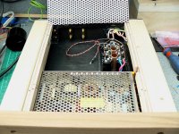
Attachments
OK Audio1st, we will be waiting for the contribution of the other members and see what we get. Thanks for your feedback!
P.
P.
By using PFC the PSU is better able to convert incoming power current into power than power supplies which do not utilize PFC. The resulting effect is lower peak and harmonic current which reduces stress on many critical components which can result in longer component life.
However I don't think this is a critical issue. I've ordered an EMI filtered switching PSU without PFC.
However I don't think this is a critical issue. I've ordered an EMI filtered switching PSU without PFC.
The schematics given in the manual quotes 220uF/50V so I guess your board is built more close to the schematics.
But then what does it mean? Does it mean I can drive the amp with a PSU rated at 50V?
But then what does it mean? Does it mean I can drive the amp with a PSU rated at 50V?
swkbkk said:
But then what does it mean? Does it mean I can drive the amp with a PSU rated at 50V?
It means you can run it at the chips max voltage of 36V...
dc offset
Oke I found out my amplifier had an dc offset of 96mV and -85mV with 30V smps. Not quite within the 10mV they listed on ebay. With a screwdriver it was easy to adjust the potentiometers to a value within 5mV. But when I connected a 12V power suply I again had a dc-offset of about 100mV. Is this strange or normal?
Another thing I noticed is that the heatsink gets hot within a few minutes after powering up with 30V. Is this normal for this chip? My TA2020 doesn't get hot at all.
Do you notice any (significant) difference in sound quality between when powering the amp with a 12V PSU and when powering the amp with a 30V PSU?
It will probably also depend on the kind of speakers being used but I just want to get some general feedback.
I already have a small SMPS rated at 12V 3A and wonder if I need to invest in a new PSU with more power to do the justice to the amp.
BTW, since my ordered unit (by mistake) is rated at 50W with a single TP2050 chip, I guess my power requirement should be less than for the one rated at 100W. But then 12V 3A is still only about 36W though.
Could you just provide me with your general feelings about the differences in the sound?
Thanks in advance!
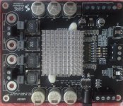
My Sure board has arrived and my heat sink also gets hot,,
Sure have added a 2n2F cap across the input under the board and I found this made the treble a tad dull, removed and has clarity now. I am running with the standard input caps to get an idea of how it sounds .
It is also dead quiet with no white noise. The Mute works on this board if you link Mute to the 5V terminal.
So far I like it..
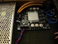
Attachments
Thanks Audio1st for your precious tweaks, I'll also remove C17 and C25. Then I'm planning to change C16 and C24 with mundorf ones (1uF I suppose)
in ordar to avoid overheating I changed the termal grease with the Zalman ZM-STG1, a great one that I recommend using even with CPUs 😉
For the inductors which gauge I have to pick?
Cheers,
KingBowser
in ordar to avoid overheating I changed the termal grease with the Zalman ZM-STG1, a great one that I recommend using even with CPUs 😉
For the inductors which gauge I have to pick?
Cheers,
KingBowser
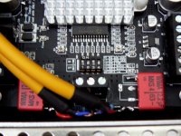
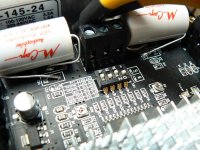
Could not resist a change of the input caps, I just needed to see what it is capable of.
The original 1uF + 220nF must have limited the low end more than I thought it would, changed to the obligatory 2u2F and can definitely hear a difference in the low notes. Also the change seems to have opened up the sound and added even more clarity. Just used what I had handy for now (Wima).
I have no inclination to change the inductors so have no suggestions in this area.
Attachments
audio1st said:Could not resist a change of the input caps, I just needed to see what it is capable of.
The original 1uF + 220nF must have limited the low end more than I thought it would, changed to the obligatory 2u2F and can definitely hear a difference in the low notes. Also the change seems to have opened up the sound and added even more clarity. Just used what I had handy for now (Wima).
I have no inclination to change the inductors so have no suggestions in this area.
On the picture I see two resistors on the input, for what are they there for? I'm still waiting for my board to come.
Regards Aleš
mravlcax said:
On the picture I see two resistors on the input, for what are they there for? I'm still waiting for my board to come.
Regards Aleš
Hi,
Those two resistors where in-place of R14 and R34, the way I have now connected the caps, the original smd resistors are back in use.
Attachments
Audio1st;
I am very new to DIY and electronics so please bear with my lame questions below:
1. On the picture with the red coloured cap, am I correct in seeing that you have replaced the original C24 (220nF) with your red one (2.2uF) and killed C25 (1uF) effectively maintaining the same capacitance at 2.2uF?
2. What benefit does this mod provide? Is it kind of replacing a low quality cap with a better quality one at the same capacitance?
3. Is it also possible to replace them with a higher capacitance, say 4.7uF and if so, will providing the higher capacitance improve the sound quality?
4. And finally what kind of monsters are the white ones? 😉
Thank you so much in advance for your expertise and time!
audio1st said:My Sure board has arrived and my heat sink also gets hot,,
Having worked with the TC2000 controller a bit, I know it's a nice chip. But it does seem to drive the output chips hot -or sometimes just warm - depending on the chip.
I suspect this has to do with the BBM (dead time) being too short. Pins 25 and 26 contol this, tho the datasheet does not say how. Usually both pins are pulled up to 5V. I would guess that pulling the pins low or open would change the BBM, just don't know how.
Will have to do some digging to find out!
Hi swkbkk
1 Yes, I have replaced the original 4 input caps for the two red caps.
2 Yes, the original caps, especially the two 1uF smd's are poor quality.
3 Replacing with anything larger than 2u2F will not make much difference to the sound, but may cause a thump through the speakers when you turn the amp on..
4 The "best" cap in the signal path is what we aim for, no cap would be better but with this type of amp that is not really an option..
Regards.
Hi Panomaniac,
Nice to see you here.
Thanks for your input, the chips get hot whether playing music or just idle, changing gain has no effect either..
I wonder if the 8 resistors between the TC2000 and the TP2050 are well matched enough, could this cause heat in the chips? The data sheet states 1% tolorence on these resistors.
Maybe the twin chip model just needs a bigger heat-sink?
Hey A1 - I still haunt the Class-D forum, just don't post as much as I used to. (you'll see me more in the loudspeaker section).
I did find the BBM settings in another datasheet.
Most designs for the TC2000 I have seen follow the datsheet and pull both BBM pins up to +5 - or "logic high." This gives a dead time of 0ns. That means low distortion, but more heat bcause of more shoot through.
I might be worth experimenting with other dead time settings. Here is a list of the settings when the pins are pulled either hi or lo.
BBM1 BBM0 Delay
0____0____120 ns
0____1____80 ns
1____0____40 ns
1____1____0 ns
A setting of 40nS ought to reduce heat without raising distortion too much.
- Status
- Not open for further replies.
- Home
- Amplifiers
- Class D
- Sure Electronics New Tripath Board tc2000+tp2050