Hi Jcx,
Can you put up a circuit sketch ? I didn't quite figure out your suggestion.
It's interesting to see that this thread is now discussing something completely different from the intended question which was " is a diode useful across the input caps that help double the voltage. In order to prevent high reverse voltage across it during switch on". I did say earlier that on reflection this was not required .
Now we are discussing the voltage doubler and why it should or should not be used.
Cool. It will lead to another subject and maybe the thread should be split here with another heading.😉
No doubt a lot of learning of several kinds has occured since !🙂
I think the discussion was about the doubler as such, not whether it is needed or not. Your rationale for its use is sound.
A doubler can be made with 2 diodes and 2 caps, while the circuit as shown had IIRC 3 caps and 6 diodes. To me it seemed needlessly complicated with no additional benefit.
I'll sketch the basic circuit in a minute unless someone else beats me 😉
jd
Sigh...............
Here is the original circuit diagram from the following page
http://www.diyaudio.com/forums/chip-amps/3857-tda7293v-4.html
OK. I'm logging off now. I have to cook dinner tonight and still have to get some additional groceries ! 😱
If I don't hurry I will not get my dose of tonight.
Here is the original circuit diagram from the following page
http://www.diyaudio.com/forums/chip-amps/3857-tda7293v-4.html
OK. I'm logging off now. I have to cook dinner tonight and still have to get some additional groceries ! 😱
If I don't hurry I will not get my dose of
tonight.Attachments
Last edited:
It sure looks like the much simpler circuit from Jan, along with its complement on the negative rail, would work just fine. Or am I missing something?
[snip] I have to cook dinner tonight and still have to get some additional groceries ! 😱
If I don't hurry I will not get my dose of
Buon appetit! Seems like you got your priorities right 😉
jd
Open, closed, what is going on with this thread?
You will get ~42V from the first circuit I posted. You won't have the ripple problems, you won't be reverse charging the caps at any point, you won't have 23V excess to get rid of and you won't have 6 unneeded components. You will have an additional winding to provide a dual rail supply if required.
This is not cool. A very short time ago you asked for this thread to be closed because it had become an embarrassment to you. Take care that it doesn't become so again.
You need to drop this 'a lot of learning of several kinds has occurred since' attitude, it's getting in the way of you learning anything. This is not some kind of social science seminar. It's an engineering tutorial. We are explaining something to you.
I have in my hand a copy of 'Horowitz & Hill', a widely admired text on electronics. At various points throughout there are sections entitled 'Circuit Ideas'. These are generally followed by sections entitled 'Bad Circuits'. These are shown for learning purposes. The original circuit posted is typical of a 'Bad Circuit' and the sooner this is accepted by all concerned the sooner some real learning will occur.
ashok, you need to disentangle your personality from your circuit ideas and grow a thicker skin. Understand that I am not trying to attack or discourage you, other than from defending a poor idea, and from imagining that you know more than you do. There are many people out there with no ideas at all and no interest in electronics and you do not fall into that category. I'd be unhappy with myself if I thought I'd caused you a serious loss of self-esteem.
w
The existing supply is about +/- 35 Vdc .
The doubler circuit provides about +/- 60 odd raw volts . This is filtered and regulated to provide about +/- 37 V dc to the input stage.
The original unregulated supply is of course required to power the output stage . The input stage however now gets a cleaned up supply .
You will get ~42V from the first circuit I posted. You won't have the ripple problems, you won't be reverse charging the caps at any point, you won't have 23V excess to get rid of and you won't have 6 unneeded components. You will have an additional winding to provide a dual rail supply if required.
Now we are discussing the voltage doubler and why it should or should not be used.
Cool. It will lead to another subject and maybe the thread should be split here with another heading.😉
No doubt a lot of learning of several kinds has occured since !🙂
This is not cool. A very short time ago you asked for this thread to be closed because it had become an embarrassment to you. Take care that it doesn't become so again.
You need to drop this 'a lot of learning of several kinds has occurred since' attitude, it's getting in the way of you learning anything. This is not some kind of social science seminar. It's an engineering tutorial. We are explaining something to you.
I have in my hand a copy of 'Horowitz & Hill', a widely admired text on electronics. At various points throughout there are sections entitled 'Circuit Ideas'. These are generally followed by sections entitled 'Bad Circuits'. These are shown for learning purposes. The original circuit posted is typical of a 'Bad Circuit' and the sooner this is accepted by all concerned the sooner some real learning will occur.
ashok, you need to disentangle your personality from your circuit ideas and grow a thicker skin. Understand that I am not trying to attack or discourage you, other than from defending a poor idea, and from imagining that you know more than you do. There are many people out there with no ideas at all and no interest in electronics and you do not fall into that category. I'd be unhappy with myself if I thought I'd caused you a serious loss of self-esteem.
w
Last edited:
...And no-one noticed the 'classic' doubler is half wave, whereas the one ashok has shown is full wave? Also, the diodes ashok has shown are required if there is any chance of overcurrent or a short on the voltage doubled rails otherwise the pump capacitors will be reverse polarized. This is also the reason why the filter cap for the doubled voltage is connected to ground and not on top of the +-V rails.
Also, wakibaki keeps explaining something which no-one asked in the thread. The circuit he posted is flawed because he failed to notice that ashoks transformer has it's center tap connected to 0V. Besides, ashok asked how to get double the voltage, that circuit is not a doubler.
Also, wakibaki keeps explaining something which no-one asked in the thread. The circuit he posted is flawed because he failed to notice that ashoks transformer has it's center tap connected to 0V. Besides, ashok asked how to get double the voltage, that circuit is not a doubler.
Last edited:
the 'classic' doubler is half wave
Wrong. Any diode/capacitor-based voltage multiplier MUST make use of both halves of the AC cycle.
Voltage Multipliers
w
Oh, I also noticed there's something wrong with ashok's numbers. He talks about 60V output, so I suspect he's putting 30v PEAK into his simulation, not 30v RMS.
Wrong. Any diode/capacitor-based voltage multiplier MUST make use of both halves of the AC cycle.
Please. This is taking things out of context - of course both half-periods have to be used or there would be no charge pump action. The point is, the one ashok gave behaves as a full-wave rectifier, with 2x mains frequency ripple, in fact it is two voltage doublers running in oposing phase. I am aware that English is not my native language but I'd like to believe the context here is very clear.
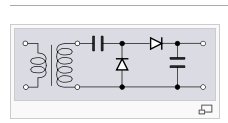
If ripple frequency were a concern then this circuit:-
...would be a more sensible starting place. The original post makes no mention of ripple frequency. The circuit in the original post is overcomplicated. The overcomplication arises not because of any concern for overcurrent or reverse polarisation in the case of a short, but because the OP has not taken the time to research the circuit, does not understand what he is doing and is attempting to design by simulation. All of which you would appreciate if you looked at the thread as a whole, instead of trying to pick an argument with me.
w
An externally hosted image should be here but it was not working when we last tested it.
...would be a more sensible starting place. The original post makes no mention of ripple frequency. The circuit in the original post is overcomplicated. The overcomplication arises not because of any concern for overcurrent or reverse polarisation in the case of a short, but because the OP has not taken the time to research the circuit, does not understand what he is doing and is attempting to design by simulation. All of which you would appreciate if you looked at the thread as a whole, instead of trying to pick an argument with me.
w
Please read post #16 and #17 where it is CLEARLY stated what the circuit is supposed to do. Then try to adapt your schematic to the problem as it is explained, and after a number of permutations of the basic concept I'm pretty sure you will arrive at a similar solution ashok has.
As for the full/half wave aspect, you might want to look into transformer net DC field imbalances caused by halfwave rectification. Generally not a problem with EI or C cores unless a fairly high current is demanded from the doubler, toriods however may buzz even with a few tens of mA of DC in the windings.
All of this of course is not apparent from ashok's initial post, but he did state he used a part of a schematic from another thread and even linked that, so it's an easy thing to look up what what the intention was, even without him explaining it when SY rightfully asked him to.
Should I still point out that indeed I have looked at the thread as a whole and that beating this dead horse is becoming an exercise in mating the unpleasant with the useless?
An externally hosted image should be here but it was not working when we last tested it.
Grounding the centre tap sure complicates things, but nobody said anything about grounding the centre tap. Now, if that had been stated as part of the original problem...
w
I forgot to add that the transformer already produces a +/- supply rail for the main circuit and the voltage doubler circuit has to use the center tap as gnd.
OK, I missed this in post #3. It seems that, not for the first time, an apology is due from me, both to ashok and to ilimzn.
w
- Status
- Not open for further replies.
- Home
- Amplifiers
- Power Supplies
- Supply voltage doubler question