Hello everybody,
this thread is not strictly related to an hi-fi amp, but based on the curiosity born some moths ago after having read this document: http://www.next-tube.com/articles/Veen2/Veen2EN.pdf
Case 5 is super-pentode, where screens are connected to the opposite UL tap, and cathode feedback is applied as usual. This gives the highest wattage without having the best possible damping factor.
So, after having seen this cheap output transformer: D29A09F | Trasformatore audio OEP, primario 6.6kΩ, secondario 3.75 Ω, 7.5 Ω, 15 Ω, 10W, Montaggio a pannello | RS Components
I though it could be a good candidate for an AB1 PP of EL84 and 6V6GT with screens connected to the opposite 20% UL tap and some shunt (instead of cathode) feedback if needed.
The choice, apart from the price, is due to small amount of feedback, so the small amount of positive screen swing while plate is going towards zero. For sure there will be need of a bigger screen resistor to control secondary emission.
I would use it for two "twins" instrument amps using 6V6GT in one power amp and EL84 in the other. I know it should go on another section of the forum, but on that specific section of the forum I wouldn't find people with experience on this kind of things, and it would become a dead thread.
Thanks in advance to everyone would like to partecipate with cogitations, impressions, suggestions or expectations. I will post some simulations in the following hours/days.
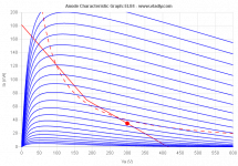
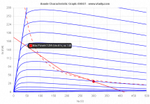
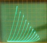
In attachment the curves of:
a -20% UL 6V6GT tube, with B+ at 300V and 6.6k Raa that should give around 23 Wrms.
a -20% UL EL84 tube, with B+ at 300V and 6.6k Raa that should give around 23 Wrms.
a -20% UL EL84 tube, with B+ at 300V and 4k Raa that should give around 23Wrms but more linearity.
a -20% UL 6V6GT tube, with B+ at 300V and 6.6k Raa that should give around 23 Wrms.
a -20% UL EL84 tube, with B+ at 300V and 6.6k Raa that should give around 23 Wrms.
a -20% UL EL84 tube, with B+ at 300V and 4k Raa that should give around 23Wrms but more linearity.
Attachments
Never tried SuperPentode. Always thought it would be difficult to stabilize.
That output tranny seems a bit marginal on power rating for 23 Watts even considering you are building an instrument amp and don't need response down to 40 Hz.
Cheers,
Ian
That output tranny seems a bit marginal on power rating for 23 Watts even considering you are building an instrument amp and don't need response down to 40 Hz.
Cheers,
Ian
Thank you Ian,
I was hoping for some feedback from you, being one of the few interested both in hi and low fi. I usually cut everything below 80 Hz in my guitar amps: I've found it gives me more freedon to equalize when with the band, without overlapping other instruments.
Do you think it won't keep up (this is the datasheet: https://docs.rs-online.com/f7be/0900766b81528910.pdf ) ?
As for stability, I would like to include local feedback to keep it controlled (and I have to say that I like how my EL34 amp breaks up with BH feedback), instead of using expensive CFB or doing the trick of grounding the 4 Ohm tap and connecting the two cathodes to the 0 and 16 Ohm tap. Do you think it won't be enough?
Worst case scenario I can connect it in pentode, or UL.
Your (simulated?) plate curves show negative resistances all over the way beyond ~100 V plate voltage. How would this work at all without Barkhausen oscillations? Remember that even those short negative resistance sections, called kinks, in usual pentodes or tetrodes (even in »kinkless« tetrodes!) may cause instabilities!
Best regards!
Best regards!
Thanks for your reply Kay!
I've used this site: Loadline calculator for power stages with reactive load - Vacuum Tube Amplifiers - DIY
for a preliminary idea of how curves would have been with negative distributed load connections only. With local feedback I expect to bring the curves back to positive resistance (as I've always seen when local nfb is applied).
These are just my expectations, I've written here to know if someone else has ever tried or has different ideas.
On that topic, I can't find anymore a pdf showing results of shunt feedback to an EL84, showing that up to 250VB+ it can bring curves back to triode-like ones, while at 300V they stay pentode-like but more linear. Has anyone seen that pdf recently?
Amplifiers with negative output resistance require a load (at all frequencies) just for the output stage to be stable. It’s possible to build solid state amps that do this (intentionally) but the amplifier/loudspeaker must be designed together as a system. You will not make it “unconditionally” stable.
If a transistor amp oscillates, it will often explode. If a tube amp oscillates, it just, well, oscillates. What might also be a concern is what is the g2 current? Especially when the plate voltage gets pulled down to 30 volts or less. It’s gotta be off the chart. And if I understand this arrangement correctly, the g2 voltage will go up when the plate comes down, making g2 dissipation go *way* up. That’s the real reason tubes like the EL84 can’t be used at very high voltages - in order to take full advantage of it you push g2 into the red.
If a transistor amp oscillates, it will often explode. If a tube amp oscillates, it just, well, oscillates. What might also be a concern is what is the g2 current? Especially when the plate voltage gets pulled down to 30 volts or less. It’s gotta be off the chart. And if I understand this arrangement correctly, the g2 voltage will go up when the plate comes down, making g2 dissipation go *way* up. That’s the real reason tubes like the EL84 can’t be used at very high voltages - in order to take full advantage of it you push g2 into the red.
Thanks wg_ski, I've not yet done simulations yet, but my expectations are that applying local feedback to the output tubes, curves will come back to positive gradient. I will confirm that hopefully soon.Amplifiers with negative output resistance require a load (at all frequencies) just for the output stage to be stable.
Yes, I wrote it in the first post. That's the reason why I kept voltages reasonably low and I will start with 1 kOhm screen resistor.What might also be a concern is what is the g2 current?
With a big screen stopper the IR drop effectively lowers screen voltage the lower you pull the plate down. Which of course protects the tubes. But the resulting curves might not look as pretty, or as compelling.
Yes, exceeding with screen stoppers, the curves will have a slope downwards when approaching the left side. I'm aware there are many incognita with this approach. That's why I hope to find someone who tried this route, but in any case I'll try it myself.
If you have expendable tubes you can always try anything. Still plenty of $3 tubes out there to play with. And hopefully you don’t magnetize an output transformer if something goes wrong.
To do so I would need to buy some cheap 6P14P, I've no cheap tubes to sacrifice in the name of R&D at the moment.
Not EL84 unfortunately.
This evening I will do some simulations and report the results.
Not being the THD a target, nor the damping factor (VOX AC30s run four EL84 in pentode mode on 4 kOhm Raa without nfb, Marshall runs his 18W with a pair of EL84 at 8 kOhm with nfb), for simulations I'd target to hit the curves close to are hit by their loadlines.
6V6GT and EL84 based guitar amps are the few ones that hit g1=0 on the left of the pentode knee, while most others hit it on the right (often through peaks of twice the max plate dissipation, when running in AB).
This "Superpentode" scheme looks unlikely to give good sound or increased power reliably and stably. Sound effects maybe. Pop-flash maybe too.
-----------------------------------------
For increased power, use a P-Mosfet follower under the tube to drive the tube cathode (V drive, used as follower). This effectively increases the plate V when more power is requested (besides providing the effective grid to cathode drive for that). Grid 1 grounded or fixed bias. (power output is tube plus driver power, keep the tube diss. portion within the tube specs)
For improved linearity besides, add a high value R-divider from plate to grid 1 to ground, as neg. Fdbk. Becoming so called "new" series Schade (CED and UnSet at Tubelab). This N Fdbk turns the tube into a top quality triode. (rivalling a 211, but with practical voltage and current ranges here).
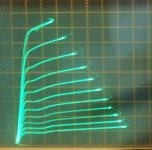
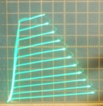
Below, curves for a $1 21HB5A TV Sweep tube in various modes. (unfortunately the 21HB5A tubes have gone up in price in the last 10 years, but most any pentode/beam tetrode will do)
1) 21HB5A native beam tet/pentode mode
2) 21HB5a new series Schade mode (CED, UnSet)
3) 21HB5a internal triode mode
4) 21HB5a Crazy drive
5) 21HB5A Crazy Fdbk (new series Schade P Mosfet drive plus Crazy drive as N Fdbk) a wire with power gain!
-----------------------------------------
For increased power, use a P-Mosfet follower under the tube to drive the tube cathode (V drive, used as follower). This effectively increases the plate V when more power is requested (besides providing the effective grid to cathode drive for that). Grid 1 grounded or fixed bias. (power output is tube plus driver power, keep the tube diss. portion within the tube specs)
For improved linearity besides, add a high value R-divider from plate to grid 1 to ground, as neg. Fdbk. Becoming so called "new" series Schade (CED and UnSet at Tubelab). This N Fdbk turns the tube into a top quality triode. (rivalling a 211, but with practical voltage and current ranges here).
Below, curves for a $1 21HB5A TV Sweep tube in various modes. (unfortunately the 21HB5A tubes have gone up in price in the last 10 years, but most any pentode/beam tetrode will do)
1) 21HB5A native beam tet/pentode mode
2) 21HB5a new series Schade mode (CED, UnSet)
3) 21HB5a internal triode mode
4) 21HB5a Crazy drive
5) 21HB5A Crazy Fdbk (new series Schade P Mosfet drive plus Crazy drive as N Fdbk) a wire with power gain!
Attachments
Last edited:
Veens "super pentode" (positive screen fb) is probably intended for partly cathode loaded outputs (neg screen fb) to restore output power at screen conditions the tube can handle.
This is really ashtonishing. During the last week I have had almost no time during the evenings, but I'd like to apply the same concept with the vertical loadline on triodes (like I've shown in the dedicated thread) instead the horizontal loadline with triodes. Gain is not 3k but around 400 in my simulations, but further work needs to be done to improve it. I'll try for sure that design in other applications.5) 21HB5A Crazy Fdbk (new series Schade P Mosfet drive plus Crazy drive as N Fdbk) a wire with power gain!
In this specific case the application is different, I'm not looking to DF nor linearity, just looking to some more watts and a different configuration to be able to use that specific transformer for guitar amplification.
This is really ashtonishing.
Crazy Feedback typically requires a LOT of drive signal thru the P Mosfet follower due to the large voltage swing on grid 2 ... (as N Fdbk) being in -series- mode. (subtracts from the drive V)
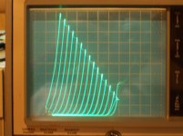
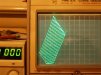
Notice I ran out of step voltage range in the curve tracer pic above for it (170 V step range max here) to show a full plate curve set. Definitely want to use a tube that works with lowish grid 2 voltages.
Could also try just grid 2 N Fdbk (with the same P Mosfet follower cathode drive). Should be close to Crazy Fdbk curves, and simpler to adjust. But will require about 20% more drive V at the Mosfet without the small grid 1 assist (of Crazy ...).
But then, that (previously -mythical- ) "wire with gain" property does beckon us to ascend the challenge. Good luck.
Last edited:
Since Crazy drive / Fdbk is linear already, the need for the cathode drive to isolate the usual "Shunt Schade" Fdbk resistor from the non-linear grid1 V is not needed.
So a Shunt Crazy Fdbk scheme should also be possible. Just the usual Crazy drive configuration with a "shunt Schade" Fdbk resistor added to grid 2 and current drive from the driver stage. This will still need grid 2 like voltage swing, besides grid 2 current (plus the N Fdbk current) drive. One may need a CCS pull-up at grid 2 to supply some idle screen current if the "Shunt Schade" resistor is not pulling enough for the screen idle current.
Edit:
Hmm, there is still a problem with this Crazy Shunt Schade scheme since the screen V and plate V are inverted in this case, so screen current will not be proportional to plate current. A Mosfet follower will be needed to drive the screen grid here.
For the cathode driven Series Crazy N Fdbk case, the screen V N Fdbk and plate V are tracking/proportional, so the screen will intercept a constant fraction of cathode current, making it appear as a constant resistance. So a grid 2 Mosfet follower may not be needed for the series Crazy Fdbk case. (at least for some gain set-ups)
Last edited:
With half a 12AX7 and the vertical loadline circuit I've obtained 250Vpp with 1.21% THD (mainly 2nd, see here: Corona: An Ultra-Low Distortion A2 DHT SE Amp Prototype ) from around 700 mVpp (gain around 360). Is it enough?Crazy Feedback typically requires a LOT of drive signal thru the P Mosfet follower due to the large voltage swing on grid 2 ... (as N Fdbk) being in -series- mode. (subtracts from the drive V)
Not for this design, but together with that gain stage, I would like to use a MOSFET concertina to drive a power amp. The goal is to find the right tube to have the right gain when setting the voltage of the loadline to half the B+, in order to DC connect the gain stage to the concertina.
- Home
- Amplifiers
- Tubes / Valves
- Superpentode-like amp: any experience with it?