
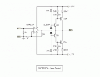
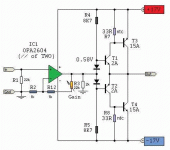
this one will work
although the bias control will not be very good, as the circuit is now
You could use small value emitter resistors for the 2A transistors
and by little by little reduce the values of two '10k' resistors,
you can set the bias of output stage to something like 1-1.5 Ampere (for Class A and +-17 Volt)
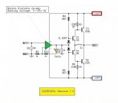
What you should do when post schematics
is to name each component with a unique name:
IC1, IC2, R1, R2, R3, C1, C2 and for transistors for example T1, T2, T3, T4
This way it is easier to talk about and refer to circuit components.
Lineup - audio regards
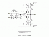
although the bias control will not be very good, as the circuit is now
You could use small value emitter resistors for the 2A transistors
and by little by little reduce the values of two '10k' resistors,
you can set the bias of output stage to something like 1-1.5 Ampere (for Class A and +-17 Volt)
What you should do when post schematics
is to name each component with a unique name:
IC1, IC2, R1, R2, R3, C1, C2 and for transistors for example T1, T2, T3, T4
This way it is easier to talk about and refer to circuit components.
Lineup - audio regards
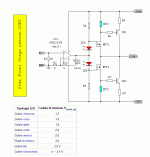
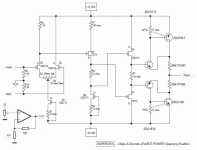
DEAR FRIENDS
now i can say that amplifier works very good
start with 0.3Vbe on final BJT (C5200 & C)
then go to very hot bias 0.7V
then stabilize on 0.5V by itself (ntc works)
live and round suond without distortion
true class A good power... try!
driver is C5171 & C
with single input signal (not two rails as normal)
this solution I probably will deliver the Nobel Prize
 🙂
🙂
now i can say that amplifier works very good
start with 0.3Vbe on final BJT (C5200 & C)
then go to very hot bias 0.7V
then stabilize on 0.5V by itself (ntc works)
live and round suond without distortion
true class A good power... try!
driver is C5171 & C
with single input signal (not two rails as normal)
this solution I probably will deliver the Nobel Prize
🙂Attachments
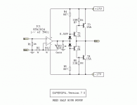
Please stop calling it igbt 🙂 ..
Sometimes, people tend to build first then post, does'nt have too look good, doesnt even have to have a circuitboard.. 😛
You're sometimes a bit fast on putting your name on the schematic are'nt you hehe..
Did it work right out from the freezer ? compensation is just that, compensation, means that it should'nt get too low when hot and so on..
- Status
- Not open for further replies.
- Home
- Amplifiers
- Solid State
- SuperOPA