Re: yes you are right
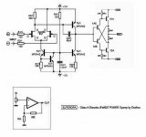
I think you got the idea from Fred Forssell's original design.
http://www.forsselltech.com/downloads/schematics/Class A JFet Opamp.PDF
Everything up to Q7 looks good.
You could have at least re drawn it. 🙂
cheers
Terry
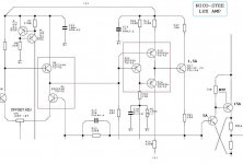
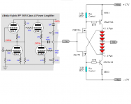
Stee said:this is just a project for 50W class A 🙄
Stee said:i have taked inspiration from Accurphase design 😉
so in the original schematic
the output bipolar was in reversal mode
but my idea is use output resistor as negative feedback
I think you got the idea from Fred Forssell's original design.
http://www.forsselltech.com/downloads/schematics/Class A JFet Opamp.PDF
Everything up to Q7 looks good.
You could have at least re drawn it. 🙂
cheers
Terry


Re: we need more power
Hi Stee,
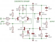
I did this amp some time ago and only completed it around June when pushed by one of my audio buddies. See if there is anything useful in it that you can use.
http://digisec.co.za/ras/music/Schematic HP Amp Rev 10.pdf
Kind regards
Nico
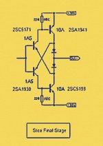
Stee said:see another cut and paste
with SFS - Stee Final Stage
most famous crossing biasing
Hi Stee,
I did this amp some time ago and only completed it around June when pushed by one of my audio buddies. See if there is anything useful in it that you can use.
http://digisec.co.za/ras/music/Schematic HP Amp Rev 10.pdf
Kind regards
Nico
Attachments
Re: NICO many thanks
Hi Stee,
You are welcome. I will keep following your amp design until it is completed and then try your design out myself. Nice going.
Nico
Stee said:🙂
best accuracy on VAS
maximum biasing on FINAL (with NTC self-control)
how many voltage can modulate this super driver? +/- 35?
Hi Stee,
You are welcome. I will keep following your amp design until it is completed and then try your design out myself. Nice going.
Nico
Re: Re: NICO many thanks
Sorry I did not answer you, what you need to watch is the power dissipation, there is quite high current flowing so choose the transistors wisely.
I have used it with 30V but was limited with what I had in my junk box.
Nico
BTW this is your design, only some small suggestions by me.
😉
Nico Ras said:
Hi Stee,
You are welcome. I will keep following your amp design until it is completed and then try your design out myself. Nice going.
Nico
Sorry I did not answer you, what you need to watch is the power dissipation, there is quite high current flowing so choose the transistors wisely.
I have used it with 30V but was limited with what I had in my junk box.
Nico
BTW this is your design, only some small suggestions by me.
😉
Re: thanks a lot Nico
Hi Stee,
I am sorry but I am not a kit person. I design something and build it, If I like it I keep it a while and then make another design.
I have gerbers of the PCB layout for this amp that I will e-mail you, but I made this particularly for a high performance headphone/line amp.
I wanted for a while to change the design for use with lateral MOSFET output stage. Maybe I do it in the next few weeks.
Cab you make PCBs?
Nico
Stee said:can you sell me one finished Amp like your pdf schematic?
then i will try to increase voltage to 60V🙄
Hi Stee,
I am sorry but I am not a kit person. I design something and build it, If I like it I keep it a while and then make another design.
I have gerbers of the PCB layout for this amp that I will e-mail you, but I made this particularly for a high performance headphone/line amp.
I wanted for a while to change the design for use with lateral MOSFET output stage. Maybe I do it in the next few weeks.
Cab you make PCBs?
Nico

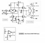
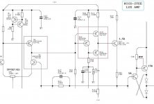
Mosfet drive variation
Now this idea come to be IGBT-similar
Because within BJT drive
There isn't any current limiting for the transistor bases.
This will most likely kill one or more parts.
for mosfet biasing need swap red leds
with a series of power diode (3x)
until have 2.1 Vsg --> Class A current 😎
Now this idea come to be IGBT-similar
Because within BJT drive
There isn't any current limiting for the transistor bases.
This will most likely kill one or more parts.
for mosfet biasing need swap red leds
with a series of power diode (3x)
until have 2.1 Vsg --> Class A current 😎
Attachments


john65b said:That expert is NOT me.
Io non sono bravo a niente!!
Oh don't be so shy, yust admit it.🙂 🙂 🙂 🙂
- Status
- Not open for further replies.
- Home
- Amplifiers
- Solid State
- SuperOPA