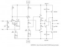
Nice topolgi.
Drivers and outputs are BJT's but shown as FETs.
You forgot the feedback.
1 ohm is a pretty high value for emitter resistors in a 50W class A amp. (Edit: and I see now they are in the collectors - is that the way to do it?)
Are the tempco of the 33ohm NTC suitable to fit the outputs BJTs PTC?
But Stee - keep on going.
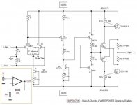
Haven't you drawn the output transistors the wrong way. I guess they should be common collector, not common emitter, or am I missing something?

Are you copying the Jung buffer input of that circuit or are you coying the darlington commomemitter driverstage?
It looks more like a Sziklai, and in that case I am not sure you can put the drivers emitters on the opposite outputs collector.
If you simulated it or build it and it works, then I am just gonna say - super - tell us how it sounds.
Otherwise check the sziklai from other amps, and see how they do.
It looks more like a Sziklai, and in that case I am not sure you can put the drivers emitters on the opposite outputs collector.
If you simulated it or build it and it works, then I am just gonna say - super - tell us how it sounds.
Otherwise check the sziklai from other amps, and see how they do.
Re: see the original
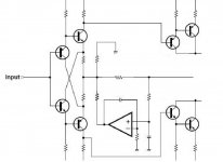
Look at the direction of the transistors to the left in this schematic. I think this is how it should be.
Since the whole schematic can't be seen, we don't really know what happens outside this fragment. It's not a Sziklai.Stee said:directly from japan
Look at the direction of the transistors to the left in this schematic. I think this is how it should be.

Re: yes you are right
This output is drawn as positive feedback, the more V across the .47 Ohm resistors the harder the output is driven. Magic smoke? 🙂
🙂
Stee said:i have taked inspiration from Accurphase design 😉
so in the original schematic
the output bipolar was in reversal mode
but my idea is use output resistor as negative feedback
This output is drawn as positive feedback, the more V across the .47 Ohm resistors the harder the output is driven. Magic smoke?
🙂Re: Re: see the original
But you are right - it is none of those - it's a Stee
I meant that Stee's output looks like a cross between a Jung buffer and a sziklai.nelsonvandal said:
It's not a Sziklai.
But you are right - it is none of those - it's a Stee
Stee: We love new revolutionary designs.
We are very much looking forward, to hear if your prototype works, and how it sounds.
We are very much looking forward, to hear if your prototype works, and how it sounds.
Can the amp use 2SA1943/2SC5200 output devices? I have lots of them....
No caps anywhere?
Any other drivers possible?
Sorry to ask....
No caps anywhere?
Any other drivers possible?
Sorry to ask....
yes you can
http://www.ampslab.com/trans_2sa1837.htm
finally an investigator who loves working group
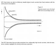
please don't forget NTC glued on power transistor
use +/- 25V with big dissipator 😉
http://www.ampslab.com/trans_2sa1837.htm
finally an investigator who loves working group
please don't forget NTC glued on power transistor
use +/- 25V with big dissipator 😉

- Status
- Not open for further replies.
- Home
- Amplifiers
- Solid State
- SuperOPA