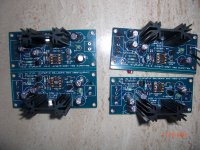
I recently bought two sets of super regulator boards and assembled them. My preferred parts supplier (Digikey.com) didn't have the BC556AP, so I used a BC557BG. I used a BC547B for the negative. Checking the spec sheets, they have exactly the same properties except for a maximal voltage of 50 rather than 80 volts.
I doubt this is related and assume that these parts work. However, to my great chagrin, my boards are not working properly. Rather than giving me the calculated output voltage, it gives me a constant +7.1V and -16.4V with the sensors properly connected. Changing the voltage divider resistor does not change the output voltage. I've checked the parts multiple times, but haven't discovered the problem. What am I missing here?
Thank you.
Last edited:
Believe it or not but this is the first time I've looked at this project. It seems to use remote load sensing... so have to ask... have you coupled the feedback loops up if you are testing it as a standalone item. If the sockets are left open it won't work.
(And if both pos and neg outputs are at pos 16.4 volts then you have a major problem... I'm guessing you didn't mean that)
Edit... there shouldn't be an issue with the parts swap at face value.
(And if both pos and neg outputs are at pos 16.4 volts then you have a major problem... I'm guessing you didn't mean that)
Edit... there shouldn't be an issue with the parts swap at face value.
I have 200 ohm power resistors loading the regulator (no sensor lines used). Other details: all the standard parts (AD825, 1k resistors -- should translate to 13.8V).
Thanks for the input Mooly
Thanks for the input Mooly
Without the sense lines connected the output won't stabilise. You need to connect them on the board if you are not using them.
The original didn't use the BC parts -- rather 2N5087 and 2N5089.
The original Panasonic caps in the SR are no longer produced.
The original Panasonic caps in the SR are no longer produced.
I experimented more with these boards today. With the sensors all connected, and a 200ohm load on the output:
Positive regulator:
17.4V in, 7.1V out
Negative regulator
-17.4V in, -16.4V out
I put the negative regulator on the scope and it showed high frequency pulsing. My boards seem to be unstable.
Playing with the voltage dividers, does not change the output voltage.
This is very disappointing and frustrating. I have some lme49710s I could try in place of the AD825s, but I doubt that would change the results.
Last edited:
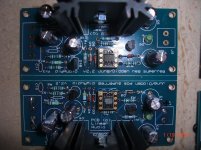
The caps are 120uF/25v Nichicons. The negative regulator of the double board has not been tested. One of the jumpers for the single positive board output sensor is underneath. I swapped out opamps in case that was the problem.
Attachments
Last edited:
The transistor sub should not make any difference, as long as you don't mix up N and P, have you verified that?
If these are the diy store boards, the pos and neg are completely separate so it's best to check them out one at a time. First only connect the pos board to the transformer/rectifier.
Find out what's going on: voltage on reservoir cap after the rectifier - does that go to the pass transistor collector?
Double check the sense line connections to the output, both gnd and hot.
Double verify polarities of diodes, sener, ref diode.
How does that all look?
Jan
I use Aries adapters which maintain the same orientation of Pin1 for the opamps, so it's difficult for me to see whether your opamps are correctly oriented on the adapter boards.
Thank you for the input Jan and Jack. I will follow your suggestions when I re-examine it tomorrow. I'll keep you posted. 🙂
I made some progress today. I have the new 2.2 version of the board and had been assuming that R15,16 and C11,12 were optional, since they were not on the schematic or the parts list. I had noticed that they were added for stability for longer sensor lines.
Putting in a 100ohm resistor and 110pf polystyrene cap (for R15,16, C11,12) made a difference. Now my negative boards are reading
Input: -17.4V
output: -15.0V
This looks good, though is surprising to me as I was assuming
V(out)=[R(total)/R(bottom)]*V(ref), which yields 2*6.9=13.8
The positive boards are still not working properly:
Input: +17.4V
output: +16.1V
The input voltages are steady and measure so on the board. For testing, I am using the output of a different regulator board for the input of the diyaudio super regulator boards.
I tested both negative boards and both positive boards, and got the same results. I also tested them after swapping LME49710 (cans) for the AD825s and got the same results with all.
Using LME49710s would yield slightly more quiet results?
Thank you again for the input.
Last edited:
To see if the reg itself is working OK and that maybe some tolerance issues cause the deviation from design values, measure the input voltages on the opamp pins.
They should be equal within a few mV. If that is the case, the reg works fine. (Measure through a few k to prevent parasitic cap to cause oscillation).
Another thing to quickly check is the opamp output voltage, it should be somewhere at the middle of Vout, assuming the output zener is about half Vout (not critical though; but if there is an eror it will be obvious).
I will review the documentation to make sure it all matches up, probably next week.
Jan
Update
The negative regulator boards work perfectly.
I never got the positive regulators working and have just looked at them again.
Input: 17.25V from another regulation stage
Output: 16.1V
The opamps all work fine - I have swapped them into the negative regulator board and it still works flawlessly.
The green LED does not light.
voltage across R1: 0.5V
voltage across R2: 16.0V
voltage across D2: -1.2V
I have an extra Q2 (I was going to make up a third positive regulator for another project, but probably will not, given that I've been unable to make the circuit work). I swapped the Q2 for a new one and get the same results.
It's absolutely baffling to me. All the parts are correct and oriented properly. The outputs are connected to the sensors. As with the negative regulator board, 1-2 and 3-4 are connected.
Any input would be appreciated. I'd rather not pitch it and go with a generic regulator.
So the positive regulator is your faulty one (in post #6 you were talking of issues with the negative one).
Answer all these questions 🙂
1/ What is your desired output voltage ?
2/ What is your input voltage ?
3/ What is the voltage across the reference generator D5 ?
4/ What value resistors have you fitted for:
R4=
R5=
R6=
R7=
Answer all these questions 🙂
1/ What is your desired output voltage ?
2/ What is your input voltage ?
3/ What is the voltage across the reference generator D5 ?
4/ What value resistors have you fitted for:
R4=
R5=
R6=
R7=
data
Thank you Mooly and Jan. Here's what I have:
I desire 15V output. My input is 17.25V regulated. I had previously had the input at 18.85V, but was advised that I could get away with a smaller V drop, so I dropped it for other reasons.
Right now
R4=499
R5=4.99k
R6=1k
R7=1k
(Vout= Vref[(R6+R7)/R7]===> 13.6V.)
Voltage across D5 = 6.85V
Voltage at opamp PINS:
2: 5.05
3: 5.69
6: 15.1
4: 0.0V
7:16.1V
Regulator input: 17.25V
Output: 16.1V
So this seems to be the case. The ref voltage across D5 is pulled down by the protection diodes (0.6 across the opamp inputs). Pin 3 is too low.
Pin 6 is too high, as if the opamp tries to increase Vout more than it can (Only 16V available).
A couple of scenarios, but my guess is that the diode in series with the opamp is the wrong way around; the opamp cannot regulate well with its output at the supply voltage. What is the voltage across that series diode?
The other possibility is that the feedback divider resistors are not the ratio they are supposed to be. Measure their resistances with all power off. If the two resistors are 1k as you say, their midpoint (pin 2) should be 8V not 5. My guess is the lower R is lower than the top R at a ratio of a half. Maybe swapped the 1k with the 499?
Jan
Last edited:
The standout error is seeing pins 2 and 3 with significantly different voltage. Having a measurable voltage difference between the two opamp inputs means the device is operating more as a comparator rather than being in linear mode.
Providing you have no construction errors you can apply a short across R6. That should force the opamp output toward ground and set the output voltage to the zener voltage of D2.
Try that. Its a good test of the basic functionality of the transistor stages.
You should see:
1/ The opamp output fall to near zero.
2/ The output voltage of the regulator settle to around 7 to 8 volts.
- Status
- Not open for further replies.
- Home
- Design & Build
- Parts
- Super Regulator Parts Substitution