I am buliding a stereo Super Leach amp this time and I do not understand where to put 4 diodes on heat sink. My amplifier has two heat sinks per one side. I put 4 PNP transistors at one and 4 NPN at the second, but where to put 4 diodes?
Thanks for help!!
Supernet
Thanks for help!!
Supernet
Drill holes and put the diodes in the holes through the heatsink in between two middle transistors on the heatsink. I could be the heatsink with either the NPN or PNP. They should run at approximately the same temperature and will keep the amplifier thermally stable. Good luck
BeanZ
BeanZ
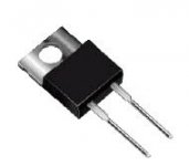
Another suggestion, I've used BYV29 diodes (see pic) for the bias circuit, they are easier to mount on the heatsinks (use also isolation!! and cooling paste).
I would use one heatsink per channel (so 2 NPN's, 2 PNP's and 2 diodes on one heatsink).
best regards,
HB.
I would use one heatsink per channel (so 2 NPN's, 2 PNP's and 2 diodes on one heatsink).
best regards,
HB.
Attachments
hugobross mentioned it but it can not be stressed enough. Make sure that you test the continuity between the tab on the TO-220 package to the heatsink. There should be no continuity! Catastrophic failure is emminent if there becomes continuity. I recommend the SIL-PADS by Berquist. They are good performers and you always know that there is not continuity.
BeanZ
BeanZ
Here is an another idea: You can use almost any PN-junction (diode) to create the -mV/degree thing. You can use isolated transistors. Connect the base to the collector, then you have a diode if you use base(collector) and emitter. You can also use (collector - base) and (emitter - base). These two types of diodes have different properties but in your application I think it's of no (or minor) importance.
The Motorola (ON Semiconductor) MJF122/127 are a fully isolated TO220 type transistor that can be used as a pair of diodes (they are a Darlington type).
I would keep the original diode scheme and put them on one of the heatsinks and see how it works. If you have problems (such as one heatsink being hotter then the other), then put 2 PNP and 2 NPN on each heatsink instead. I talked to Dr. Leach about this a few months ago, when I was considering seperate heatsinks for my superamp, and I think he suggested 2 and 2 with the diodes on one, but I can't remember exactly, since i found a heatsink with 8 - to-3 holes to use instead.
Good luck,
--
Brian
Good luck,
--
Brian
Actually, the 122/127 is not a good idea. There is a low value resistor around one BE junction. I wish the STV4H bias diodes were still available. NTE still has the three junction ones, but no four junction ones.
Do you still need to use 4 BYV29 like you normally have to use 4 1N4004 diodes?? Please let me know as it would be a good modification.
Cheers
Bowdown
Cheers
Bowdown
hugobross said:Another suggestion, I've used BYV29 diodes (see pic) for the bias circuit, they are easier to mount on the heatsinks (use also isolation!! and cooling paste).
I would use one heatsink per channel (so 2 NPN's, 2 PNP's and 2 diodes on one heatsink).
best regards,
HB.
I think this is not a good idea. Mr. Leach used the diodes istead of the normal power transistor to reduce the capacity between the sensing device, and the heatsink. If You apply 4xTO220 diodes You will get 4 times capacity, and it will reduce the bandwidth (and even decrease the stability margin).
So I recommend to use the four diodes, and mount two of them to the NPN heatsink, and two of them to the PNP heatsink. With transistors, any small signal type is OK with 5mm hole in the heasink and use some glue to fix them.
sajti
So what your saying is i should be ok using 1 or 2 of the TO220 type diodes?Please if anyone else has any suggestions please help as this would benifit lots of other diyers...
Regards
Bowdown
Regards
Bowdown
I suggest to use the diodes as recommended by Mr. Leach. 4 of them, and put them to the heatsink, with glue.
sajti
sajti
If you have NPN transistors on one heatsink and PNP on another, you mount two diodes on each sink. At least, thats what Mr Leach says in his FAQ.
You are supposed to drill small holes for the diodes to go into and then glue them there, so that they have maximum coupling for sensing the heat.
You are supposed to drill small holes for the diodes to go into and then glue them there, so that they have maximum coupling for sensing the heat.
- Status
- Not open for further replies.
- Home
- Amplifiers
- Solid State
- Super Leach diode problem