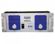
hello to everyone. I follow the forum and greatly appreciate the high level of discussion. This is my first post in the forum. I am rebuilding an amplifier of 80 years, and would like suggestions to replace all the transistors and other components that result in improvement for most current devices. I would be very grateful for any help. Attached goes the photo of the "thing" andtechnical data are:
Sorry about the english.
POWER: 400 Watts RMS p / channel (4 ohms)
P 250 WATTS RMS / channel (8 ohms)
. FREQUENCY RESPONSE: 10 Hz to 80 kHz - 3 dB
. Intermodulation Distortion: Less than 0.02%
. THD 100 W @ 4 Ω: less than 0.01%
. Damping Factor: 300 at 1 kHz (8 ohms)
. NOT BALANCED INPUT IMPEDANCE: 30 K ohms
. Input Sensitivity: 1.23 volts (+ 4 dB)
. Signal to Noise: Better than 95 dB
. MINIMUM LOAD IMPEDANCE: 4 OHMS
. CIRCUIT CLASS: AB
. WEIGHT: 20.2 Kg
. DIMENSIONS: L: 19 "A: 7" - 4U P: 14 "
. POWER: 115 / 230 VOLTS
. 115 VOLTS MAXIMUM CONSUMPTION: 1400 WATTS
Attachments
Welcome. I doubt if your amp is 80 years old, transistors weren't invented until 1958. Usually when I rework an amp over 25 years old, I replace the electrolytic caps and the tin plated RCA connectors. Band use amps can have worn out banana jacks or 1/4 phone jacks. On amps with a fan, I replace it with a long life model. Of course, general cleaning of dust dirt and new filters is good practice, especially the heat sinks. I use water and a paper towel, sometimes a little bathroom cleanser like scrubbing bubbles, but I put it on the paper towel. A pick is required to scrape around the tiny components.
For example, the 47 uf cap near Q4 and the 100 uf cap near Q5 are probably electrolytic. You may have other larger more seriously dried up caps in the power supply near the transformer. All these caps will have a plus on one lead, or a minus sign in balls pointing to the minus lead. Most consumer products were built with 1000 hour rated caps sealed with rubber (electrolytic caps have water in them). A T and M prefer to measure the caps for value & ESR before replacing, but the meter to do that is $150 or $90 kit. I just replace them, they are not very expensive. If the amp is working now, replace 1 or two parts at a time and test that it sounds okay or better after that, to prove your solder joint and parts quality.If not backup and rework, or rethink. I buy all the electrolytic caps at once, to save on freight, which is much as 100 small caps. You can buy 3000-8000 hour rated caps if you try, these will last longer than 25 years perhaps. Farnell.com has the hours rating in the selector table, other vendor like mouser link to the manufacturer's datasheet, which you have to read. They stock a lot of cheap short life caps, so it takes some work to screen them out. Also, surplus caps on E-bay etc may be long into their shelf life, or even past it. I buy surplus film and ceramic caps, but not electrolytic caps.
The transistors tend not to be defective unless the amp has been abused by shorted speaker wires, bad fan, or a shorted capacitor. If the amp is dead, another set of test and measurement skills is required, report back.
I'm listening right now to a 197? FM radio, through a 1970 build 1966 design dynakit amp. The radio performance was severly improved by recapping 2 years ago. The dynakit was recapped, but had semiconductor issues caused by poor heat management. Have fun with your amp.
When testing with the cover off, don't wear jewelry, and touch things one hand at a time. Over 24 VDC, if the current crosses your heart, can stop it.
Last edited:
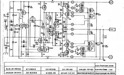
Hello Indianajo. Sorry for the mistake. The amplifier was manufactured in 1980. I would likesuggestions to replace the old 2N5400, 2n5415, BD139, BD140 transistors by more current, lower noise, or better technical characteristics. The output of MJ15xx were destroyed .. I already bought these in FARNELL (On Semiconductor). I got the electrolyte source, are of the GIGAELCO low ESR, temperature of 105C. The diodes are replaced by a bridge 50A/1000v. Thanks for the post and any help is welcome.
After an output transistor meltdown, I have been informed that bringing it up gradually with light bulbs in series with the power cord, or in my case, a switchless 1500 watt room heater, is important for not stressing the O.T.'s. When I didn't, I blew another PNP O.T that had passed the double diode test, and it took out a new opposite NPN transistor. I had a lot of 1n4148's etc blown in my most recent transistor amp, and another leaky one just damaged an op amp, so in future after a meltdown I'm going to test them backwards with a 19VDC source and measure the current with the DVM, instead of using the DVM ohms scale which is 9v max. After the amp doesn't put DC out on the speaker hot line (I had a lot of trouble with that, burned PCB lands) then you can check your idle current on the O.T. emmiter resistors. My amp is reading 30 mv on .5 ohm emmiter resistors, so I guess a cold idle current of 15 ma is okay. I put terminal strips on the amp to make this measurement convenient from the t
Search under the parts forum for the 10 favorite BJT transistors. Mooly had a great list. I tend to buy whatever transistors farnell has on sale with enough Vceo and current rating, as my biggest noise
generator is still my op amp mixer I use to boost the magnetic phono and mix the FM radio with the CD player. With the mixer powered down, the ST120 amp is quieter than the fans I put on it. I used NTE49, NTE50, NTE249, and NTE60 transistors, all NPN, because that is what the stocking distributor had in town in 1985 when I repaired the amp. They are a bit pricey, and nothing special except for the high Vceo (the st120 runs 80 V Vcc) It is quiet enough now, the fan at the factory across the street 100 m away is noisier.
op.
Your emmiter resistors appear to be 0.1 ohm, so matching of the output transistors is probably important.
The experts on here say matching the saturated on voltage is more important than matching the gain. You may have to build a jig to do that, using a dvm. I don't have to on this amp I'm repairing, it has 0.5 ohm emmiter resistors and the service manual says it is designed to not require O.T. matching.
Last edited:
Here is a list of favorite transistors not mine: http://www.diyaudio.com/forums/parts/143349-best-transistors-have-hand.html
I'm listening to one of the worst reviewed amps of all time the dynakit ST120, and it sounds better than my "legendary" St70 tube amp with new caps and output tubes. I think the secret is 1. the djoffe crossover distortion mod which solves a problem of low bias current your Sony won't have 2. faster output transistors, the NTE60's. Somebody did a simulation on a very early transistor amp, the Leak 70, which came with 2n3772's. Each time they put faster O.T.'s in the simulation it says the distortion got lower. That is where I am on the St120. It came with house number 1970 RCA ouput transistors probably selected from the 2n3055 process, which were slow (Ft) and low gain. I put in NTE 60 O.T's which were probably equivalent to MJ15003's at the time, and did the "TIP" mod which slows down edges with BE capacitors to avoid oscillation. Result- better than the tube ST70 amp, equivalent to the CS800s amp (1998) on top octave piano. (my distortion test, I compare a good piano record with an actual Steinway piano). Thus if you use MJ15024's or MJE21194's or something modern & fast for O.T's, if it doesn't oscillate due to the extra speed, you might get more accuracy. This is a theory, you can do the sim, perhaps. On the St120 I've still got one channel of TO5 1970 driver transistors; it doesn't sound worse than the channel with the 1985 NTE 249, NTE49, and NTE50 to92 and TO200 transistors.
I'm listening to one of the worst reviewed amps of all time the dynakit ST120, and it sounds better than my "legendary" St70 tube amp with new caps and output tubes. I think the secret is 1. the djoffe crossover distortion mod which solves a problem of low bias current your Sony won't have 2. faster output transistors, the NTE60's. Somebody did a simulation on a very early transistor amp, the Leak 70, which came with 2n3772's. Each time they put faster O.T.'s in the simulation it says the distortion got lower. That is where I am on the St120. It came with house number 1970 RCA ouput transistors probably selected from the 2n3055 process, which were slow (Ft) and low gain. I put in NTE 60 O.T's which were probably equivalent to MJ15003's at the time, and did the "TIP" mod which slows down edges with BE capacitors to avoid oscillation. Result- better than the tube ST70 amp, equivalent to the CS800s amp (1998) on top octave piano. (my distortion test, I compare a good piano record with an actual Steinway piano). Thus if you use MJ15024's or MJE21194's or something modern & fast for O.T's, if it doesn't oscillate due to the extra speed, you might get more accuracy. This is a theory, you can do the sim, perhaps. On the St120 I've still got one channel of TO5 1970 driver transistors; it doesn't sound worse than the channel with the 1985 NTE 249, NTE49, and NTE50 to92 and TO200 transistors.
Last edited:
Hello Indianajo and llwhtt. Sorry about the delay, I was researching Dynaco ST416. Thanks for the tips. The emitter resistors are 0.1 ohm actually, I take care to combine the output transistors. I saw the NTE60/61 replacement as an option to MJ15xxx. But the output transistors are in a configuration feature that improves its response, so I thought about keeping them. llwht I didn't know the similarity between the schemes. Thank you! The amplifier does not have the pre of Dynaco. It hasn't output inductor and other small circuits, but the channel follows the same configuration. I'll look more closely at the changes and inform. It was of great help. Sorry about the English.
Here is Mooly's list of favorite BJ transistors http://www.diyaudio.com/forums/parts/197440-if-you-could-only-buy-10-bjt-transistors-ones.html
I looked at buying some of these last time but they are pretty expensive at Farnell, over $.50 small signal and over $2 TO220. Might be worth it if you are looking for the best.
I think the NTE60 might be equivalent to the MJ15003 , not superior. Just what the retail shop had in stock. NTE is way too expensive now that we have the internet and can buy the real thing.
Hablo un poco del espanol, pero el puertoguese es differente, no? No se preoccupa usted por su engles.
Last edited:
Yes the amplifier circuit is the same minus the "Dynaguard" and part of the power supply which is for the ICs. Since this is a James Bongiorno design you could start by following his recommendations, replace all pf sized ceramic compensation capacitors with like value Silvered Micas and replace the ceramic bypasses with same value film capacitors. Most of the transistors in your amp are much more recent than when the ST416 was made and are still available new. Many of the original Dynaco semis are long gone. That output stage was used in Ampzillas and SAEs of the period. Another simple upgrade would be to replace the 5-10% carbon resistors with 1% metal films. Also replace all of the small electrolytic capacitors with Panasonics or Nichicons.
After reading your post it got me interested in pulling my Dyna ST400 off the shelf and get it up and running again but as luck would have it I picked up two Luxman B-12s this weekend so those are going to get fixed first. So back to the shelf goes the Dynaco, again.
Craig
After reading your post it got me interested in pulling my Dyna ST400 off the shelf and get it up and running again but as luck would have it I picked up two Luxman B-12s this weekend so those are going to get fixed first. So back to the shelf goes the Dynaco, again.
Craig
Hello and Indianajo llwhtt. I seek information from the amplifier that you will work llwhtt, read a little about the Ampzilla and James Bongiorno, as well as on the Dinakit Indianajo. This gave me more courage for my endeavor. The blend of appearance, outputstage and driver stage of the amp I'm working on made me think of a new name for the amplifier. Lol. Very cool DC amp the Luxman B-12. Good technical data. I do not think an amplifier easy to find, and not low price. The amplifier I'm rebuilding will receive new vu, new “guard” printboard, and a painting. I think I'll replace all components. I want all original and from the same manufacturer, and a new wiring also, of course. Thanks for the tips.
Post here a picture of a Toshiba set (M12, T10, SY-C12) I have, of good quality. Aurex - Aurex System 15, Aurex System 12, Aurex System 10, Aurex Toshiba
Post here a picture of a Toshiba set (M12, T10, SY-C12) I have, of good quality. Aurex - Aurex System 15, Aurex System 12, Aurex System 10, Aurex Toshiba
Good morning. The mica capacitors are very expensive. Each capacitor is more expensive than the output transistors. What other could I use instead? Can I use the film in place of all ceramic tile?
Thank you.
Thank you.
Mostly ceramic caps are used for the low self inductance which allows them to suppress Radio Frequencies (RF). For example the 0.1 uf cap on the output, and the 1000 pf cap near Q6. These both should be ceramic or mica. Film caps are mostly wound, with a medium self inductance. There are new technology stacked film caps for switched mode power supplies, I don't know how the self inductance rates against ceramic caps. You must make sure Sony used no COG dielectric ceramics, which is temperature sensitive. Another thing you can do can reduce Z5U ceramic non-linearity is increase the voltage rating to the 50V maximum. If your ceramic caps don't have explicit voltage ratings but have a letter after the capacitance, then check the letter against the voltage ratings in the manufacturers datasheet. I've used some 50V aerovox gold ceramic caps in place of tantalum caps as input couplers, and with a <1.3V signal they sound quite acceptable. The original tantalum caps were low value, and the replacement tantalum caps had a frying pan noise.
I find the idea of replacing the wiring a bit strange. I only do this only when my amateur soldering skills have damaged the insulation. Then I replace with teflon insulated wiring, which is available from surplus houses at attractive prices. This will withstand the waving around of the soldering iron, and some of it is silver plated also.
I find the idea of replacing the wiring a bit strange. I only do this only when my amateur soldering skills have damaged the insulation. Then I replace with teflon insulated wiring, which is available from surplus houses at attractive prices. This will withstand the waving around of the soldering iron, and some of it is silver plated also.
Last edited:
Hello Indianajo. I will then keep the ceramic capacitors, mica are unfortunately very expensive. I will rely on the project over the ST416, the type and voltages of each capacitor. The amplifier is not in good condition, and I'm literally rebuilding. Some circuit boards, I'll have to rebuild. The amplifier has damaged tracks on the circuit boards of the output. I'll redo it. The board of the soft start is with moisture, and the relay does not look good. All capacitors have approximately 30 years. The transistors can not be trusted, some resistors do not keep the original values when measured (were heated). So I'll rebuild it entirely.
The transformer is ignorance and an amplifier that had an incredible robustness, greater than my more modern amp. I spend about $ 300 parts. It's big, clumsy, ugly, but I really want to hear it again. The sound was great. As soon as possible, put some photos. Thank you.
The transformer is ignorance and an amplifier that had an incredible robustness, greater than my more modern amp. I spend about $ 300 parts. It's big, clumsy, ugly, but I really want to hear it again. The sound was great. As soon as possible, put some photos. Thank you.
Heat damaged carbon comp resistors are frequently over value. I replace them with metal film resistors from multicomp or vishay at farnell. these have been made in India so far and on value. Metal film resistors are quieter than carbon comp in higher values (100k and over).
When replacing burnt circuit traces, I lift the component leads at the end and wrap the wire around the lead to get a good mechanical bond before soldering.
You'll need a couple of big resistors to test the amp output when done to prove it is not putting out DC. So buy them now and check the output of the power transformer with the resistors and a DVM AC meter. There is no point in spending money on components if the power transformer is damaged. I use 225 watt resistors, 10 ohm variable tap ones for 8 ohm mainly amps and 5 ohm fixed value ones for 4 ohm mainly amps.
I found NJW21194 transistors were $2.50 cheaper than MJ15003 at farnell. I used MJ21195 for PNP because it saved $1 each. I don't buy transistors on E-bay, too many fakes around.
I'm listening to a 1970 build ST120 amp right now. It has a great transformer. Besides a transistor meltdown when I bought it, the design has heat management and transistor crossover bias issues. I installed a djoffe bias circuit with heat sensing modifications and a pair of fans on the heat sink (no fins) to keep it from thermally running away.
Last edited:
- Status
- Not open for further replies.
- Home
- Amplifiers
- Solid State
- Suggestions to replace ?