Trying to make a power supply for a mic that requires +70v -70v. I found the TL783 for regulating +70v but haven't found anything to regulate the -70v.
Any suggestions, tricks, schematics, tips would be awesome. 🙂 thanks
Any suggestions, tricks, schematics, tips would be awesome. 🙂 thanks
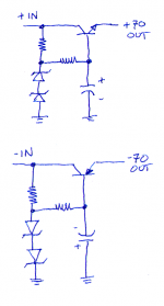
For such low currents that may happen in mic & preamps, a zener diode
is sufficient, for both the rails. You might want the zeners and the resistors
to be 1/2 W. Add two more decoupling capacitors and you've got a six components voltage regulator for + and - 70 V.
is sufficient, for both the rails. You might want the zeners and the resistors
to be 1/2 W. Add two more decoupling capacitors and you've got a six components voltage regulator for + and - 70 V.
My suppliers don't stock 70 volt zener diodes but they do stock the NZX36, 1N5258, and 1N4753, all of which are 36 volt zeners. So you could build zener regulated, capacitance multipled supplies using MJE340 / MJE350 as series pass regulators. 6 components per rail.
Attachments
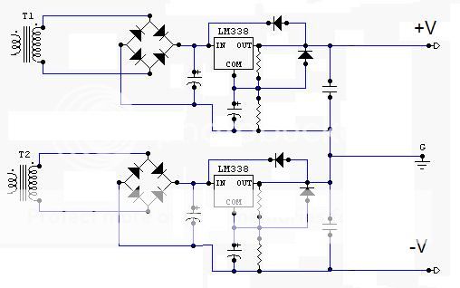
if you have two secondaries, you can use a positive chip regulator "upside down" as it were, to regulate the voltage between the ground and the negative. you must form the ground point after both regs, not before
also, you can use a lower voltage regulator and attach zeners to the adjust to take it up, so long as the drop between Vin and Vout doesn't exceed spec, and you don't short the output by accident
also, you can use a lower voltage regulator and attach zeners to the adjust to take it up, so long as the drop between Vin and Vout doesn't exceed spec, and you don't short the output by accident
if you have two secondaries, you can use a positive chip regulator "upside down" as it were, to regulate the voltage between the ground and the negative. you must form the ground point after both regs, not before
also, you can use a lower voltage regulator and attach zeners to the adjust to take it up, so long as the drop between Vin and Vout doesn't exceed spec, and you don't short the output by accident
do you have an example schematic for your first suggestion?
If you're using a 3-terminal regulator, just using a sufficiently large resistor on the Adj pin could work. Take a look at the application notes; there's a wealth of information there on power supply design.
Alternatively, this might be a case where shunt regulation makes sense. I have a hunch that could be electrically quieter than using a zener. I assume that a microphone needs very quiet supply rails.
Alternatively, this might be a case where shunt regulation makes sense. I have a hunch that could be electrically quieter than using a zener. I assume that a microphone needs very quiet supply rails.
do you have an example schematic for your first suggestion?

protection diodes, caps, resistor values, should all be as datasheet
I have always wonderd about the PSRR of a mic, and can never find any info. Luckily the standard 48V phantom power is easily regulated with a LM317HVIf you're using a 3-terminal regulator, just using a sufficiently large resistor on the Adj pin could work. Take a look at the application notes; there's a wealth of information there on power supply design.
Alternatively, this might be a case where shunt regulation makes sense. I have a hunch that could be electrically quieter than using a zener. I assume that a microphone needs very quiet supply rails.
Thanks for that schematic Robert. That totally helps.
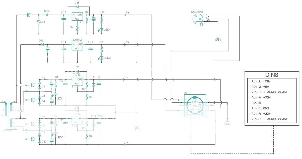
this might be a stupid question but say I also wanted 5v. Can i add another LM7805 to one of the windings or would I need another winding to do that with this set up? Thanks
this might be a stupid question but say I also wanted 5v. Can i add another LM7805 to one of the windings or would I need another winding to do that with this set up? Thanks
You will be dissipating a LOT of energy to get 5v out of that. I would use a winding that is closer to your intended output voltage.
You will be dissipating a LOT of energy to get 5v out of that. I would use a winding that is closer to your intended output voltage.
well my plan was to use a voltage quadrupler to get the 70v.
Last edited:
Here this is what I had in mind... Would this work or am I in need of exclusive windings? thanks.


well I tested the schematic above, it works, but now the 70v rails are uneven.😕
any suggestions on how to compensate? Could this just be a case of tweaking resister values? Or any design techniques anyone can share? thanks in advance.
any suggestions on how to compensate? Could this just be a case of tweaking resister values? Or any design techniques anyone can share? thanks in advance.
Could this just be a case of tweaking resister values?
Yes. the reg's ref voltage is usually listed as 1.2 to 1.3V. So potentially up to 8% difference between any 2 units. So tweak resistors to compensate.
You can use the "2 Transistor Regulator" from Jones "Valve Amplifiers" -- the output voltage will be ~2x the value of the reference. It's good to around 40-50mA and very simple to implement.
For more current use a Darlington transistor as the pass element.
An externally hosted image should be here but it was not working when we last tested it.
For more current use a Darlington transistor as the pass element.
- Status
- Not open for further replies.
- Home
- Amplifiers
- Power Supplies
- Suggestions on regulating -70v
