I've built a full wave voltage doubler on the output of an SMPS from eBay.
(DC-AC Converter 12V to 110V 200V 220V 280V 150W Inverter Boost Board Transformer | eBay)
I have it set to 200V output and get 420V through the doubler (22uf in the "bridge" 100uf on the output).
All I had were standard diodes (1N4007, 1N5408x2 in series) which it says in the write up will be heated and fail quickly which they did after 10 minutes.
The DC output on the board uses HER207 so I'm guessing I could use any diode with similar characteristics?
Any suggestions would be great. Current draw is about 30ma@420VDC.
Thanks.
HER207 are readily available. Very fast 2amp diodes!
HER207 | HY Electronic Corp HER207 Fast Recovery Diode, 800V 2A, 75ns, 2-Pin DO-15 | HY Electronic Corp
HER207 | HY Electronic Corp HER207 Fast Recovery Diode, 800V 2A, 75ns, 2-Pin DO-15 | HY Electronic Corp
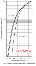
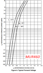
I'd recommend you use diodes rated for at least 3A forward current, at least 600 volts reverse breakdown, reverse recovery time less than 200 nsec, and as low a forward voltage drop as possible.
Perhaps the Vishay VS-ETL0806 datasheet#1 or the ON Semiconductor MUR460 datasheet#2 might fit the requirements nicely. Both are widely available at distributors like Element-14, Mouser, DigiKey, Avnet etc.
Their forward voltage curves are attached below.
_
Perhaps the Vishay VS-ETL0806 datasheet#1 or the ON Semiconductor MUR460 datasheet#2 might fit the requirements nicely. Both are widely available at distributors like Element-14, Mouser, DigiKey, Avnet etc.
Their forward voltage curves are attached below.
_
Attachments
I've built a full wave voltage doubler on the output of an SMPS from eBay.
It appears that you have used the common voltage doubler (across the 0-200V taps on secondary side), often referred to as full-wave, although the capacitors see half-wave pulses.
You also have the option of using the slightly more complex (full-wave for the capacitors) voltage doubler using a CT connection - although this could only be applied using the 0-110-220V taps.
Image link from Jochen's High Voltage Page : Basic multiplier circuits

Note that these circuits assume a ground at the capacitor centre-point - but that can be moved to the 'neg' output terminal.
Cheap Chinese caps with no datasheet, and no I haven't. It's a cheap 150W supply that I'm asking for 12W from. I'm not worried, I just needed faster diodes apparently.
The supply has filtered DC output as well as AC. I get 420VDC from the 200V AC side. steady current is ~30ma
I'm using the first style doubler because it was just simpler. I'm using it for class a tube audio and there is no measurable noise with my scope connected to the output and the input shorted to ground. I call that a win!
Cheers.
Last edited:
Yeh, I ordered 2 yesterday to check out performance.
I like the secondary CT, simple regulator, and small footprint. The other 230VAC 'car inverters' that have the same simple PP primary I've looked at just use a single secondary winding and full bridge rectifier, but include a mains frequency H bridge (which is just removed), and often a USB output.
The single-ended flyback pcbs (eg. YH11068A) have a nice low idle power consumption of 0.5W, so it will be interesting what the idle loss is for this PP drive smps.
That pcb looks easy to add some judicious smt ceramic caps to minimise switching transient current loops in the main power and regulator circuits. But I couldn't make out from the ebay photos if it included output voltage feedback.
- Status
- This old topic is closed. If you want to reopen this topic, contact a moderator using the "Report Post" button.
- Home
- Design & Build
- Parts
- Suggestions needed for a diode to rectify 37kHz