Hi everyone,
I'm trying to design a tube buffer based on a pretty linear tube operating in the medium voltage range. In this case, the voltage I can obtain is about 120 V (from a voltage doubler). I took a look on two possible tubes like ECC88 or EF95, but if there are other possible candidates they are welcome. I read a very nice tube is 6SN7 but has minimal distortion only for fair high anodic voltages.
The project wich I refer to is here:
Audiocostruzioni - Il Portale dell'alta fedelt? amatoriale
I'd like to bring some change to preamp stage, relating to voltage and maybe the tube too. Thanks.
A 6DJ8 would work reasonably well at that voltage, but a cathode follower is reasonably high in PSRR, so a quadrupler wouldn't be a bad idea, and then you can run a 6SN7 well.
Also, you can run a CCS instead of the load resistor to give back some of that voltage the triode is standing on, giving the tube more breathing room.
Here's a overengineered and lovely design from our very own Sy that I have built (the non-servo version will work great in the majority of applications, and you can even build it without the input transformer if you please) and will do pretty well-
Heretical Preamplifier
I'm fixing to build another with affordable (but high quality) edcor input transformers, and a 6N16B russian submini tube for my input selector build.
Last edited:
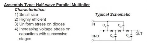
For a voltage quadrupler, the 1/2 wave parallel topology provided works reasonably well. Large valued caps. in the multiplier are essential and only 1/8 of the AC RMS current being rectified is available as B+ DC. TANSTAAFL.
I suggest you scan the archives for my posts regarding "hash" filters. Following the multiplier, a "hash" filter and then a LC reservoir section will result in "clean" DC. Schottky diodes in the multiplier eliminate switching noise, but the big caps. necessary still result in noise that should be removed.
I suggest you scan the archives for my posts regarding "hash" filters. Following the multiplier, a "hash" filter and then a LC reservoir section will result in "clean" DC. Schottky diodes in the multiplier eliminate switching noise, but the big caps. necessary still result in noise that should be removed.
Attachments
Yes, I was thinking to quadruplicate the voltage (keeping in mind that each step I will lose mA), anyway if the plate current is fair low to keep all stable I will consider it. I'll take a look for some topology in PSU, like those you said.
At the moment the trasformer I would use has three secondary outputs: 5,6 - 28,5 and 43 VAC. So it can be useful for the heaters too (for 6N... etc tube types)
A last question, somewhere I read another way to raise the voltage...at the secondary output of the first transformer another transformer, set reversed so 12V->220 , was connected to get the desired voltage. Is this a good idea? It seems you may risk to burn something...
I read it here: Tube buffer
Another idea would be to use 6P43P tubes connected in triode. They will work nicely at 40V. Scroll down to the bottom.
Tube Tester Files - EL82, EL84, EL86 Soviet Clones
Tube Tester Files - EL82, EL84, EL86 Soviet Clones
Yes, it would't be a bad idea, maybe for the future, but for now I'd prefer to go to a known route. By the way, I made some calculation for the cathode follower with the ECC88, I hope it's right:
V(cathode) = 220V - 150V = 70V
R(c) = V(plate)/i(c) = 220/22 -> 10 kohm (2 watt)
R(b) = V(bias)/Ia = 4/0.007 -> 560 ohm (1 watt)
The last ones both derived from the ECC88 diagram, by choosing the parameter Ug=-4V and Ia=22 mA, with Ua=220V
RI(internal resistance)=5k
RL(load) =10K
Av = (RL*mu /(RL + ra)) / (1 + [RL*mu / (RL + ra)]) = 0.96 (from datasheet)
Rin = ((RI + (mu+2)*RL) / (RI + (2*RL))) * Rg = 1 Mohm (choosing Rg=68K)
C(in) =0.33u
C(out) =4.7u
Attachments

Yes, it would't be a bad idea,
Seems OK. Dividing the power supply into ⅓'s is good. 70 volt VK (kathode in german) relative to ground. 220 V VA. Plenty of "buffer" headroom.
In point of fact, unless you have unusual front-end requirements, it almost makes no difference. Choose VK to be anything from 20 V to 150 V (for your 220 V power supply). There are rarely input signals requiring more than ±7 VP₂P (peak to peak). So "70" is as good as any other number mid-range.
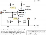
The big "gotcha" tho' is that you'll have to go for a "raised grid". Not sure any of your diagrams have that. Essentially, you set up a high-Ω voltage divider to be the "raised" voltage you're trying to achieve. Say "70 volts": Shooting for a CLEAN voltage divider (you don't really want to amplify power supply hum) is key.
Using the notation RHI and RLO, I'd use a
RHI = 220 kΩ
RLO = 68 kΩ … in series.
this gives a Thevenin equivalent resistance of REQ = 51 kΩ and a divided voltage of +68 volts.
Connect grid of buffer to that via another 330 kΩ resistor. Place (on the voltage divider) a nice small 2.2 μF capacitor (250 V) for "filtering". 68 V leg to ground.
Then you'll get your 70 volt VK. As you intend.
It'll be running at 6.8 ma at 10 kΩ RK. ½ watt. Use a 1 watter if you like.
GoatGuy
PS the "SYclotron" heretical preamplifier is a good idea too. Only problem is to get really high quality transformers. And they're “pretty spendy” for the good ones. I myself like cap-coupled. Caps work, they're cheap, the "sonic impact" is far, far, far oversold.
PPS: the RHI and RLO resistors were chosen not "out of the blue" but with something in mind: coming up with a 68 volt "grid supply" that'd have an equivalent resistance below 100 kΩ. I actually have something just as arbitrarily chosen (in values) working right at the moment. Been in operation for near 15 years. "It works".
PPS: the RHI and RLO resistors were chosen not "out of the blue" but with something in mind: coming up with a 68 volt "grid supply" that'd have an equivalent resistance below 100 kΩ. I actually have something just as arbitrarily chosen (in values) working right at the moment. Been in operation for near 15 years. "It works".
Seems OK. <snip>
If I understood well is this a fixed biased CF you say? Effectively, among other things it offers a lower input impedance too
A last question, somewhere I read another way to raise the voltage...at the secondary output of the first transformer another transformer, set reversed so 12V->220 , was connected to get the desired voltage. Is this a good idea? It seems you may risk to burn something...
I read it here: Tube buffer
I used it to, read below.
6N16 12x preamp srpp/cathode follower with printed circuit board design.
i am getting 155v from a voltage doubler hung off the 50v dc supply and using 32v winding from sx-780.
the 155v is regulated down to 140v for noise free B+.
I am using 10uf / 250v caps for the AC connection. The output sags about 5v (150v) with a 20ma load for 6922 preamp.
inversing the transformer works well as long as you use equal or less input voltage and keep the load at or below the transformer VA rating. ( watts of load)
Last edited:
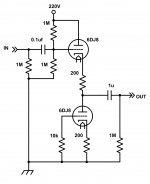
Not really. Consider the attached diagram. Better mathematicians than me have demonstrated that the input impedance can be VERY high with cathode-followers. I prefer them more controlled, as indicated. With a 330 kohm bias-to-grid ballast resistor, the input impedance will be REQ (51 Kohm) + 330 khom or about 380 Kohm. High enough.
gg
gg
Attachments
") So, it is certainly worth trying (as other here confirm that works well for the purpose)
So, it is certainly worth trying (as other here confirm that works well for the purpose)Yes, I took a look. It's a good PSU topology, with double PI filter at the output...seems well regulated.
The diagram says medium to high mu triode. For good performance as a cathode follower you need high gm, not high mu. For use with lowish supply rails and lowish value load resistances (as seen in that circuit) you need lowish mu.GoatGuy said:Consider the attached diagram.
Where does the 51k come from?With a 330 kohm bias-to-grid ballast resistor, the input impedance will be REQ (51 Kohm) + 330 khom or about 380 Kohm.
The diagram says medium to high mu triode. For good performance as a cathode follower you need high gm, not high mu. For use with lowish supply rails and lowish value load resistances (as seen in that circuit) you need lowish mu.
Where does the 51k come from?
Ah… mu and gm. They're quite different. Yet also related 'sort of'. But you are right: high gm is needed. Thanks.
51 kΩ come from? 220 khom || 68 khom. Thevenin equivalent resistance of a resistive voltage divider voltage source. For others (I hardly need remind you, esteemed one!), a voltage divider for all intents and purposes acts like the divided voltage source in series with an equivalent resistor. Good ol' Dr. Thevenin came up with that. Useful abstraction.
GoatGuy
The diagram says medium to high mu triode. For good performance as a cathode follower you need high gm, not high mu. For use with lowish supply rails and lowish value load resistances (as seen in that circuit) you need lowish mu.
Biipolar PSU and ECC86/6GM8, with (possibly) CCS loading of the CFs?
- Status
- This old topic is closed. If you want to reopen this topic, contact a moderator using the "Report Post" button.
- Home
- Amplifiers
- Tubes / Valves
- Suggestion for a tube buffer