H
HAYK
The inputs of the chip are inverters with 60k resistors. The source impedance adds to this resistor and un balances the two feedbacks. As the negative is grounded, the positive should also be of minimum impedance. 10k pot. is 2.5k max. 50k is 12.5k. See post 17
https://www.diyaudio.com/community/...ss-d-into-abd-modulation.396664/#post-7290300
https://www.diyaudio.com/community/...ss-d-into-abd-modulation.396664/#post-7290300
Ok, great, thanks HAYK. I'll look for a quality 10k pot then.
Sorry about re-asking, but will 24V 3A be sufficient for two channels of 30w, or do I really need a 24V 4A power supply?
Once I know that answer I can begin purchasing parts!
Thanks again
Sorry about re-asking, but will 24V 3A be sufficient for two channels of 30w, or do I really need a 24V 4A power supply?
Once I know that answer I can begin purchasing parts!
Thanks again
H
HAYK
It is sufficient. Does it have Earth input? If so, you don't need EMI filter.
How much it costs?
How much it costs?
I posted it a little before - I think it is similar to the one you recommended to me except it is rated up to 3A and a little smaller physically:
https://www.aliexpress.com/item/100...5!sea!AU!762615254&curPageLogUid=DHL7Xw0HNdEI
From what I can tell it doesn't have an earth input so I will still need the EMI filter. It costs a few $ cheaper than the 4A version.
What do you think?
Thanks again!
https://www.aliexpress.com/item/100...5!sea!AU!762615254&curPageLogUid=DHL7Xw0HNdEI
From what I can tell it doesn't have an earth input so I will still need the EMI filter. It costs a few $ cheaper than the 4A version.
What do you think?
Thanks again!
H
HAYK
Thanks for all your advice HAYK. I have ordered all the parts. Came to $140AU all up, as I got better shipping on most items to speed the process up.
I can't wait hehe.
I can't wait hehe.
Hi everyone,
I had a question about the possiblility of implementing a subwoofer output into this amp.
By doing so, I will open up more potential subwoofers to purchase that don't have speaker-level inputs and only have a single RCA input.
My goal is to have the audio come into the amp via the RCA the binding posts at the back, go through the volume pot and then the output of the volume pot goes to the inputs of both the left and right channel amps for the speakers but also has a downmixed mono RCA port that can be connected to a subwoofer. I want the volume control of my amp to also change the volume of the audio going to the subwoofer so they stay volume-matched.
Am I correct in the idea that I split off the output from the volume pot, through a series resistor on the non-ground lead, one for both left and right channel, then join the output of the resistors together before soldering that to the RCA post at the back of the amp to be connected to the subwoofer?
I've attached a terrible ms-paint dialog of what I mean. Scenario 1 is what would normally be set up, and scenario 2 is the one I am hoping to do.
Also, would the 220ohm 2w resistors I have purchased also work for this case?

The kind of subwoofer I am talking about is something like this:

Thanks for your help!
I had a question about the possiblility of implementing a subwoofer output into this amp.
By doing so, I will open up more potential subwoofers to purchase that don't have speaker-level inputs and only have a single RCA input.
My goal is to have the audio come into the amp via the RCA the binding posts at the back, go through the volume pot and then the output of the volume pot goes to the inputs of both the left and right channel amps for the speakers but also has a downmixed mono RCA port that can be connected to a subwoofer. I want the volume control of my amp to also change the volume of the audio going to the subwoofer so they stay volume-matched.
Am I correct in the idea that I split off the output from the volume pot, through a series resistor on the non-ground lead, one for both left and right channel, then join the output of the resistors together before soldering that to the RCA post at the back of the amp to be connected to the subwoofer?
I've attached a terrible ms-paint dialog of what I mean. Scenario 1 is what would normally be set up, and scenario 2 is the one I am hoping to do.
Also, would the 220ohm 2w resistors I have purchased also work for this case?
The kind of subwoofer I am talking about is something like this:
Thanks for your help!
H
HAYK
You need >100k resistors to mix the two channels. You need to know the input impedance of the subwoofer if 50k source can drive it full power.
Does the back of the board indicate that shorting those will put it in stand-by? Or vice versa? So possibly an on-off switch?
Hi HAYK,
I almost have all the parts delivered, but I wanted to double check on the mods you mentioned are good to do with the amps.
I have attached a picture below. I know I need to remove the SMD output caps, and solder a leg of each of the blue caps to the output of the black things on the board, join the other leg and connect to two parallel 2w resistors, but where to I solder the output leg of the resistors to? I can't tell from the picture you uploaded in the other thread.
Thanks so much for your help!
H
HAYK
In Post #27 you have miswired the Alps potentiometers. If you hook them up like that, your amp will be perfectly silent 😛...
And you can certainly make a chip amp work with lower gain than the usual datasheet circuit suggests. I've made some mistakes along the way, but the end result worked out just fine.
Here's the thread: https://www.diyaudio.com/community/threads/fun-with-a-cheap-tda2030a-at-only-6db-gain.345259/
And you can certainly make a chip amp work with lower gain than the usual datasheet circuit suggests. I've made some mistakes along the way, but the end result worked out just fine.
Here's the thread: https://www.diyaudio.com/community/threads/fun-with-a-cheap-tda2030a-at-only-6db-gain.345259/
Ah thanks Preamp, I'll double check the wiring of them. It was just a rough diagram, I'll make sure I get the correct cables in the right spots on the potentiomer.
HAYK, just to double check what you mean, I've completed the diagram as far as I understand you have explained it.
If you say it looks good, I'll be able to get the soldering iron out soon hehe!
I've attached the final guide below.
Thanks again for all your help and I'll post back with more progress as I have it!
Hey bros, just a small update - all the parts have arrived! I will attempt to fit everything into the smallest case that I found that can just fit everything!
This is the case that I chose: https://www.aliexpress.com/item/100....order_list.order_list_main.11.5df81802hWWIyt
I have 3d modelled in FreeCad a base plate that will hold all of the PCBs that make up this amplifier and facilitate easy connection between the parts.
It is printing now, I'll see if the print worked overnight tomorrow and whether I need to make any changes to the tolerances and reprint.
I'm also toying with the idea of 3D printing the backplate as well, rather than bothering to drill through the aluminum. Might end up being easier, I'll see!
Hi fellas,
Just as an update, the 3D print of the base and back plate together as the same object fits nicely.
The print warped a little but thankfully not enough for me to need to do another print.
Now that the base plate is printed and the parts all fit I will try soldering as much of it together tonight as I can.
I am still waiting on a friend to drill the volume pot hole into the front plate so sadly I can't finish the amp tonight, but hopefully by next week it will be!
If anyone is interested in the part that I designed to be 3D printed to work for this amp and pieces please let me know and I will try to attach it.

Hey fellas,
I've been going back and forward a few times on the design but have now settled on a separate power supply design.
For the few minutes I have had the amp working properly I can confirm that the noise floor is much better than any other amp I have.
I have however run into a few issues with it so far.
The main thing is, at the moment, the amp works very well for 1-2 mins, but then static noise seems to increase in one of the channels. When I remove power and wait a bit, and start again the noise isn't there, but after 1-2 mins it starts again.
I've blown a few of the mono amp PCBs. Once when I let the noise accumulate for too long one of the channels blew as well.
Does this point to something wrong with the large capacitors I am using with the build? Or is the problem likely somewhere else?
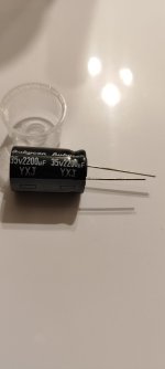
Does anyone have any suggestions? I have attached a picture of the capacitors I am using.
Thanks for any help in advance.
I've been going back and forward a few times on the design but have now settled on a separate power supply design.
For the few minutes I have had the amp working properly I can confirm that the noise floor is much better than any other amp I have.
I have however run into a few issues with it so far.
The main thing is, at the moment, the amp works very well for 1-2 mins, but then static noise seems to increase in one of the channels. When I remove power and wait a bit, and start again the noise isn't there, but after 1-2 mins it starts again.
I've blown a few of the mono amp PCBs. Once when I let the noise accumulate for too long one of the channels blew as well.
Does this point to something wrong with the large capacitors I am using with the build? Or is the problem likely somewhere else?
Does anyone have any suggestions? I have attached a picture of the capacitors I am using.
Thanks for any help in advance.
Attachments
- Home
- Amplifiers
- Chip Amps
- Suggested affordable quiet amp for high efficiency speakers